Download
1 / 47
470 likes | 592 Views
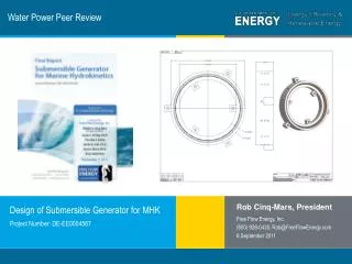
Water Power Peer Review. Rob Cinq-Mars, President. Free Flow Energy, Inc. (800) 928-0435; Rob@FreeFlowEnergy.com 6 September 2011. Project Number: DE-EE0004567. Design of Submersible Generator for MHK. Purpose, Objectives. The design of a submersible generator – key features:

E N D
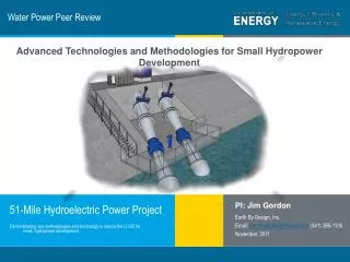
Water Power Peer Review Rob Cinq-Mars, President Free Flow Energy, Inc. (800) 928-0435; Rob@FreeFlowEnergy.com 6 September 2011 Project Number: DE-EE0004567 Design of Submersible Generator for MHK
Purpose, Objectives The design of a submersible generator – key features: • designed by motor/generator industry professionals • work with multiple turbine styles • critical subassembly of current energy conversion systems Objectives: • accelerate MHK • improving performance • lowering cost, and • improve operation and maintenance
Technical Approach - Tasks • Assess resources tidal and river for: • proper sizing • form factor • power rating • ambient operating conditions. • Determine appropriate topology • Electromagnetic circuit design • Mechanical design • Investigate Manufacturing Requirements • Cost Analysis • Commercialization and future research
Technical Approach – Key Issues • MHK Generators - where wind generators were in ‘70s • Eliminate gearbox (Rim Mount Design) • Get topology, sizing, power and form factor right • Components designed/manufactured by industry • Work with multiple turbines • Design for harsh marine environment • Coupling method
Schedule & Budget Schedule • Initiation date:11/1/2010 • Planned completion date: 10/31/2011 • Design Completed, report published, paperwork complete Budget: • On schedule, on budget, additional cost share provided
Project - Preliminary • Differences between renewable and conventional generation • Appreciate difference between power, energy and nameplate capacity • Differences between tidal and inland stream flows • Design for common siting conditions not extreme / rare • Lessons learned from wind • Many different turbine styles, sizes, & stages of development • Review and understanding of MHK state of art • Understanding of regulatory, permitting, siting • Acceptance of 35% efficiency • Baseline estimate of “realistic” siting conditions
Resource Assessment - Tidal What’s Realistic?
Resource Assessment - Area Area & # Turbines to Generate 1 MW Assumes 35% eff (Gorlov)
Resource Assessment - Tidal UK Current Predictions
Resource Assessment - Tidal Tacoma Narrow Currents
Resource Assessment - Tidal Maine, Washington, and AK Velocity Frequency Histograms
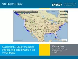
Resource Assessment - Tidal Most recently – Georgia Tech / DOE Model, Mid Atlantic Currents
Resource Assessment - Tidal Mid – Atlantic Depths
Resource Assessment – Inland USGS Field Descriptions
Resource Assessment - Inland Channel Velocity (mps)
Channel Area - Inland USGS Inland Data – Channel Area (m^2)
Resource Assessment Cont. Depth: 10 – 30 m (Top: Nav Clearance, Bottom: Permitted Sites) Salinity: 35 ppt Temp: 35-90 F, 2-32 C
Analysis of turbines Proprietary data was shared with FFE based upon completed NDAs. Data included CAD, test data, estimated torque / speed, TSR, etc. This data was used to design a generator with a 2 meter diameter rated at 20 kW to connect to a 3m x 7m GHT, or an equivalent FloDesign turbine which presents a 5 m diameter to the flow. This is approximately 21 m^2 in cross section. Comparable dynamic performance…
Selection of appropriate topology Induction or Synchronous? (Field winding not reasonable) AF, RF, or TF? Gearbox for speed? (Rim mount) Iron core or coreless (magnet use and detent torque) Pole Count: more poles more voltage more power (balancing act) Cost and manufacturability Selection: RFPM Synchronous as wind is evolving to.
Gearbox Issue Shaft seals are an issue, bow wakes, velocity fluctuations we selected rim mount speed enhancement with 2 m diameter
What others do… Air core? Transverse Flux? Weight reduction? Increased magnet use
What others do… SmartMotor Claims: concentrated windings, higher fill factor, higher efficiency It appears from the description that this generator uses large gauge wire, hand inserted.
What others do… VIEG – Variable Input Electrical Generator This appears to be a “stacked generator.” They appear to be dynamically connecting windings in series at low speed and parallel at high. This appears to be quite costly, like purchasing multiple generators for one site.
Our generator Radial flux, permanent magnet, synchronous, three phase, rim mount (2 meter diameter, 20 kW in 2 m/sec flow) A conventional, buildable, cost effective approach capable of coupling to multiple turbine designs. The design leverages established and simple manufacturing processes.
Other Work Completed Cost Analysis Manufacturability Tooling and Fixturing Requirements Protective Coatings Refer to Final Report
Conclusion Delivered what was proposed… the design of a submersible generator capable of coupling to multiple turbine styles, designed by motor/generator design engineers specifically for MHK Needed: Turbines to move closer to production Diversions to accelerate flow A greater indication of commercial viability
Moving forward: embracing diversions http://www.youtube.com/watch?v=hEnANV8laRU