FGT electronics integration – reminder/update
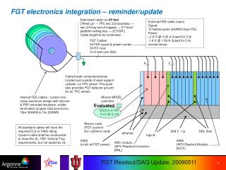
FGT electronics integration – reminder/update. Estimated cable run 65 feet [ West cyl → TPC sec 2/3 boundary → sec 2/3 tray out of magnet → 2 nd level platform ceiling tray → 2C7/8/9 ] Cable length to be minimized…. External FEE cable (each) Signal: 15 twisted pairs (24AWG foam PE) Power:

FGT electronics integration – reminder/update
E N D
Presentation Transcript
FGT electronics integration – reminder/update Estimated cable run 65 feet [ West cyl → TPC sec 2/3 boundary → sec 2/3 tray out of magnet → 2nd level platform ceiling tray → 2C7/8/9 ] Cable length to be minimized… External FEE cable (each) Signal: 15 twisted pairs (24AWG foam PE) Power: +1.8 V @ 0.90 A (fused for 3 A) -1.8 V @ 1.56 A (fused for 5 A) remote sense FGT Cables 24 FEE signal & power combo 24 HV coax (4 of each per disk) 8 2 Cable break connectors/boxes located just outside of west support cylinder, on TPC wheel. This point also provides FGT detector ground tie (to TPC wheel). Internal FEE cables: custom low-mass aluminum design with silicone & FEP extruded insulation, solder terminated (copper clad aluminum), 15pr 30AWG & 10c 22AWG Wiener MPOD controller Evaluated ISEG 8 ch HV -4 kV @ 2 mA Wiener crate (FGT custom) 6U x 220mm cards All standard cables will have the required CL2 or CMG rating. Custom cable shall be constructed to meet the UL-1581 Vertical Tray requirements, but not tested by UL 208 V 1 φ DDL fiber ethernet trig/clk SGIS (to kill all FGT power) ARM (APV Readout Module) [IUCF] ARC module (APV Readout Controller) [ANL]
FGT FEE – readout interface • Is defined by the cable connector board; this is the interface • IUCF has designed and fabricated a prototype cable connector board • Addresses the crucial question of whether the FEE – RDO interface can be carried over long cables, permitting platform-mounted RDO UART/I2C bridge CLK/TRG buffer LDO voltage regulator
Connector board prototype • Mounts directly onto two MIT APV boards at outer radius of FGT • Prototype uses bulky/massive cable connector just for convenience – actual connector board will be directly terminated to Cu/Al cable • Soldered wires and custom plastic support frame / strain relief • Dimensions (prototype): 75 mm square • Shown here with old (single APV) board for preliminary long cable tests; awaiting real FGT APV boards for final tests
Readout board frontend prototype and long cable test A typical APV event, 128 channels’ data (here only pedestals) • Demonstrated basic operation of APV • 170% of planned cable length • Equalization filter designed and tested • ADC (anti-alias) filter design in progress • Tests with Struck ADC module and full FGT APV board within next weeks 110 feet Belden #1424A Slow controls PC
FGT readout crate electronics update • Working on selection of backplane to connect readout controller to APV readout modules • Plan to use standard commercial backplane with sufficient connectivity but define our own simplistic protocol; just use the traces. • Two obvious choices : VME64x and cPCI cPCI VME64x
FGT readout electronics update • Assuming 7-slot configuration • Available in both connector styles, a few advantages for cPCI thanks to higher pin count of “hard metric” 2mm connector. • cPCI 32-bit has ~same number of bussed connections as VME64x but adds 32 pins for signals to pass through backplane to transition (cable receiver?) card. • Direct cable connection to pass-thru pins a possibility. • cPCI 64-bit replaces pass-thru pins by 32 extra bussed lines. • cPCI has request/grant signal pair per slot for readout control (all control in master), whereas VME64x uses daisy chain • VME64x has one signal line (common clock to all boards), whereas cPCI has one clock wire per slot (star distribution) • Currently in process of requesting quotes to compare prices. • Pin utilization estimate: • 32 signals used for readout data • 16 signals used for control address/data • Another ~12 pins for clocks, resets, strobes and token passing
Current tasks • Complete long cable test with full APV boards and external ADC • This will include pulse height spectrum, test pulser, possibly test w/ charge-sharing prototype @ MIT • Defines (confirms) the interface FEE – readout system • Rack allocation can proceed • Aluminum inner cables will be procured • MIT proceeds w/ final APV board design • Defines the readout board (ARM) frontend circuits • With ADC chip selection, full readout board design will commence • Finalize crate backplane choice and pin assignments • Crate procurement can proceed • Finalize interfaces of ARC (controller) module including DAQ data format • Full controller board design will commence