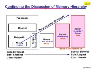
ERD Memory Discussion
ERD Memory Discussion. Victor Zhirnov April 10, 2011 Potsdam, Germany. ERD Memory Tasks. Update Memory Tables and Text Implement the decisions made at the 2010 ERD FFM as well as at the 2010 workshops in Barza and Tsukuba Status: work in progress 1 st draft (tables): April 2011

ERD Memory Discussion
E N D
Presentation Transcript
ERD Memory Discussion Victor Zhirnov April 10, 2011 Potsdam, Germany
ERD Memory Tasks • Update Memory Tables and Text • Implement the decisions made at the 2010 ERD FFM as well as at the 2010 workshops in Barza and Tsukuba • Status: work in progress • 1st draft (tables): April 2011 • Final draft (tables + text): July 1, 2011 • Create new section on Storage Class Memory • Status: 1st draft completed • Final draft: April 2011 • Create new section on Select Device • Status: 1st draft completed • A fundamental study is underway develop an analysis of nanoscale selector devices for memory • Final draft: July 1, 2011 • Research paper: November 2011
Decisions for Memory Section (Dec. 2 & 5, 2010 ERD Meetings) • Put Vertical MOSFET in the Memory Section • Include new section on Storage Class Memory • Include new section on Select Device
2010 Important Events • Emerging Research Memory Devices Workshop • Barza, Italy, April 2, 2010 • Emerging Memory Materials workshop • Tsukuba, Japan, November 30, 2010
2009 ERD Memory Table PIDS Redox Memory Mott Memory
Summary : STT RAM– 1st Place in voting • Pros • Well defined physical Model and simulation tool. Very fast improvement. Many chip level papers on IEDM, VLSI and ISSCC • No control device needed (for apple to apple comp. STT RAM vs. Other ReRAM w/ control device) • CMOS compatible and No HV ease of front end integration. • Extendibility : ~1uA Writing current @ 50ns speed ( 50nm diameter P –MTJ @IEDM2009) Even In plane MTJ can be extendible) • Scalable than PCRAM, Nanothermal and Nano electronic memory w.r.t write speed, endurance(>1E12) and retention. • 4F2 possible by vertical tr.(Currently ~21F2, 40nm and chip level) • MTJ can be extended to logic devices as an nonvolatile unit. • Cons • MLC operation and stacking is difficult • Very much process dependent : • - MgO dielectric Reliability ( subsequent temp. and etching ) • - Thermal instability(< 150C) , different from single cell results. • - Even endurance as low as 1E7(chip level) • - Hc shift and stuck at 1 or 0 status. • - Variation • All parameters are related each other. Need to decouple(ex. retention , programming current, RA, TMR , endurance, speed), Keeping in mind memory is simple device.) Much better developed technology than other ERD memory entries – time to migrate to PIDS
Nanothermal and Nanoionic Resistive Switching Memories: A Summary – 2nd place • Classification • ‘Nanothermal’ and ‘Nanoinic’ often refer to the same mechanisms of resistive switching • Decision: To merge ‘Nanothermal’ and ‘Nanoionic’ in one category – RedOx Memory • Scaling properties • Based on fundamental physics, Nanothermal/Nanoionic memories may be scalable to 10 nm (and below), capable to fast (~ns) operation • Current Application Prospects • Unclear in the context of existing memory hierarchy • Incomplete understanding of operation mechanisms • Lack of predictive models etc.
2009 ERD:Electronic Effect Resistive Switching Memories • Charge trapping induced resistive switching • Resistive switching induced by Mott-transition • Ferroelectric resistive switching • Ferroelectric tunnel junction (FTJ)
Electronic Effect Resistive Switching Memories: A Summary • Charge trapping induced resistive switching • A non-workable concept • Should not be considered in the future • Resistive switching induced by Mott-transition • Needs to be investigated under benchmark values • Ferroelectric resistive switching • Needs to be investigated under benchmark values • Issues: Retention, endurance fatigue, scalability
Ferroelectric resistive switching • Interesting concept • Ferroelectric tunnel junction - FTJ • Not really “electronic effects memory” • Operation principle is based on ferroelectric polarization, similar to e.g. FeFET • Same difficult problems as in FeFET • Retention, endurance fatigue, scalability • Much smaller number of research papers compared to other types of ReRAM
Changes in the 2011 ERD Memory section • To take out the “electronic effect memories” entry from the ERD memory table • The Ferroelectric Tunel Junction memory could be covered along with FeFET as a subcategory • Action Item: A new name for ERD ferroelectric memory entry is needed • Mott Memory will form a stand-alone entry
Resistive switching induced by Mott-transition: An optimistic view • Very interesting concept (believed by enthusiasts to be the ultimate solution for nanodevices) Silicon-based contemporary electronic devices based on a naive electrostatic charging are reaching their miniaturization limits... Alternative ideas are craved: for example, using phase transitions rather than the charge storage…The ultimate resistance-change device is believed to exploit a purely electronic phase change such as the Mott transition… I. H. Inoue and M. J. Rozenberg ,”Taming the Mott Transition for a Novel Mott Transistor”, Adv. Funct. Mater. 2008, 18, 2289–2292
Mott memory issues: I- Research Activity • Much smaller number of research papers compared to other types of ReRAM • Most of the papers are theoretical • In experiments, different conductive mechanisms may contribute to the resistive switching • Only a few experimental works presenting evidences for Mott transition R. Fors, S. I. Khartsev, and A. M. Grishin, ‘Giant resistance switching in metal-insulator-manganite junctions: Evidence for Mott transition’ , PHYS. REV. B 71, 045305 (2005)
Mott memory issues: II – Scaling An Chen: Although switching devices on the scale of 200 nm has been shown to have the characteristics similar to these observed in larger devices, this size is far from being competitive to existing memory technologies. More research on the size effect of the Mott transition properties is needed to address the fundamental scaling limit of this type of devices. • Scaling of Mott devices might be a problem • What is the minimum number of atoms in a Mott memory element to provide retention and sensing properties? • Needs to be investigated under benchmark values
Action Item: A new name for ERD ferroelectric memory entry is needed • Combines two subcategories: • Ferroelectric FET • Ferroelectric tunnel junction • Should not be confused with conventional ferroelectric memory or FeRAM • Based on FE capacitor • Is currently in PIDS • Temporary working name: • Ferroelectric effects memory • Suggestions are welcome
Memory Select Device TWG: Wei Lu (U Michigan)An Chen (GLOBALFND) Kwok Ng (SRC)Victor Zhirnov (SRC) The fundamental study team Dirk Wouters (IMEC) Rainer Waser (U Aachen) Thomas Vogelsang (RAMBUS) Zoran Krivokapic(GLOBALFND) Al Fazio (Intel) Kyu Min (Intel) U-In Chung (Samsung) Matthew Marinella (Sandia Labs)
ReRAM Select Device: Transistor Conventional approach Diode Other 2-terminal non-linear element? Enables cell scaling to 4F2 Supports 3D-stacking Potentially lower cost etc.
General remarks on Memory Select Device • The select device is a non-linear element, which can operate as a switch. • Typical examples: transistors (e.g. FET or BJT) or diodes. • Up to now, FET is commonly used as select device in practical memory arrays, such as DRAM or flash. • In order to achieve the highest planar array density of 4F2, without considerable overheads associated with vertical select FETs, passive memory arrays with two-terminal select device are currently actively investigated where two-terminal devices with switch-type behavior (e.g. diodes) are integrated in series with resistive storage nodes in a cross-bar array.
Transistor-type select devices • In order to reach the highest possible 2-D memory density of 4F2, a vertical select transistor needs to be used • the approach being currently actively pursuit. • While vertical select transistor allows for the highest planar array density, this 4F2 technology is more difficult to integrate into stacked 3D memory, than the conventional 8F2 technology using planar FETs • to avoid thermal stress on the memory elements on the existing layers, the processing temperature of the vertical transistor as selection devices in 3D stacks has to be low, which is not available for high-quality transistors). • Also, making contact to the third terminal (gate) of vertical FET constitutes additional integration challenge.
Decisions for Memory Section (Dec. 2 & 5, 2010 ERD Meetings) OK • Put Vertical MOSFET in the Memory Section • Include new section on Storage Class Memory • Include new section on Select Device
Two-terminal Select Device • Diode-type select devices • pn-diode, • Schottky diode • and heterojunction diode • Zener or avalanche diodes. • Resistive-Switch-type select devices • innovative device concepts that exhibit resistive switching behavior. • in some of these concepts the device structure/physics of operation is similar to the structure of the storage node. • A modified memory element could act as select device! • a ‘nonvolatile’ switch is required for the storage node, while for select device depending on the approaches non-volatility may not be necessary and can sometimes be detrimental. Unipolar cell Bipolar cell
Selection Device Benchmarking • ‘Waser 2010’ (individual cell-based) • Von ~ 1 Volt • Ion min ~ 1 mA • Jon ~106 A/cm2 for L~10 nm • ‘Hwang 2010’( cross bar array with a 1-100 Mb block density) • Von ~ 1-5 Volt • Jon ~ 105 – 106 A/cm2 • ON/OFF > 107-108 H. Schroeder, V. V. Zhirnov, R. K. Cavin, and R. Waser, “Voltage-time dilemma of pure electronic mechanisms in resistive switching memory cells ”, J. Appl. Phys. 107 (2010) 054517 G. H. Kim, K. M. Kim, J. Y. Seok, H. J. Lee, D-Y. Cho, J. H. Han and C. S. Hwang, “A theoretical model for Schottky diodes for excluding the sneak current in cross bar array resistive memory”, Nanotechnology 21 (2010) 385202
Resistive-Switch-type select devices I • Mott-transition switch • is based on the Mott Metal-Insulator transition • a volatile resistive switch, • A VO2-based Mott-transition device has been demonstrated as a selection device for NiOx RRAM element [Ref: M.J. Lee, “Two Series Oxide Resistors Applicable to High Speed and High Density Nonvolatile Memory,” Adv. Mater. 19, 3919 (2007).]. • The feasibility of the Mott-transition switch as selection devices still needs further research. • Threshold switch • is based the threshold switching in MIM structures caused by electronic charge injection/trapping • Significant resistance reduction can occur at a threshold voltage and this low-resistance state quickly recovers to the original high-resistance state when the applied voltage falls below a holding voltage.
Resistive-Switch-type select devices II • MIEC switch • observed in materials that conduct both ions and electronic charges – so called mixed ionic electronic conduction materials (MIEC). • The resistive switching mechanism is similar to the ionic memories. • Complementary resistive switch • the memory cell is composed of two identical non-volatile ReRAM switches connected back-to-back. • Example: Pt/GeSe/Cu/GeSe/Pt structure • Electrically, it can be represented by a antiserial connections of two intrinsic Schottky diodes, which are formed at the contact sides of both cells • Can be placed into the category of Diode-type select devices
Resistive-Switch-type select devices Source: Philip Wong / Stanford
Criteria for the evaluation of selection devices (An Chen/GF)
Scaling limits of two-terminal semiconductor non-linear elements Victor Zhirnov1, Kwok Ng1, An Chen2, Wei Lu3 1Semiconductor Research Corporation 2GlobalFoundaries 3University of Michigan
I V 2-terminal selector devices • External selecting device OR storage element with inherent rectifying/isolation properties • 2-terminal structure with non-linear characteristics • e.g. switching diode-type behavior for unipolar memory cells • for bipolar cells, selectors with two-way switching behavior are needed, e.g. Zener diode, avalanche diode etc. ION1 ON2 ION OFF ON1 OFF unipolar bipolar
Selection Device Benchmarking • ‘Waser 2010’ (individual cell-based) • Von ~ 1 Volt • Ion min ~ 1 mA • Jon ~106 A/cm2 for L~10 nm • ‘Hwang 2010’( cross bar array with a 1-100 Mb block density) • Von ~ 1-5 Volt • Jon ~ 105 – 106 A/cm2 • ON/OFF > 107-108 H. Schroeder, V. V. Zhirnov, R. K. Cavin, and R. Waser, “Voltage-time dilemma of pure electronic mechanisms in resistive switching memory cells ”, J. Appl. Phys. 107 (2010) 054517 G. H. Kim, K. M. Kim, J. Y. Seok, H. J. Lee, D-Y. Cho, J. H. Han and C. S. Hwang, “A theoretical model for Schottky diodes for excluding the sneak current in cross bar array resistive memory”, Nanotechnology 21 (2010) 385202
I. Scaling Limits of the Schottky Diodes Energy barriers (Schottky barriers) are formed at the metal-semiconductor (insulator) interfaces space charge formation in the interface region If the barrier profile is known, the calculation of the current passing through the barrier is straightforward based on the thermionic and tunneling equations
Excel-based home-made diode model: A calibration C.Y. Chang, Y. K. Fang, and S. M. Sze, “Specific contact resistance of metal-semiconductor barriers”, Soli-State Electron. 14 (1971) 541-550
Scaling limitation: Reduction of the effective conduction area due to side depletion • If finite lateral dimensions of a 3-dimensional semiconductor structure are considered, the side interfaces can also effect the current flow. • Band bending/barrier formation usually occurs at these interfaces, and they need to be taken into account. • The band bending results in either depletion (bent up) or accumulation (bent down), and correspondingly, a layer with lower (depletion) or higher (accumulation) conductivity of width WSV is formed. • Therefore, in addition to the depletion WMS layer aligned with the direction of current (‘active’ interface, modulated by external stimulus), there is a lateral depletion layer WSV perpendicular to the current flow (‘passive’ interface, which remains more or less stable during device operation). • This ‘passive’ side interface may also effect the total current. If a depletion high-resistive layer of width WSV is formed, the effective cross-sectional area for modulated current flow is decreased. • In the case of an accumulation low-resistive layer, a parasitic surface resistor will be formed in parallel with the resistive memory element.
Reduction of the effective conduction area due to side depletion Imin=1 mA WSV WSV Lmin>2W0 L Nd
Scaling Limits of Diodes Me Me Si Nd≤NC pn-diode Esaki tunnel diode NdNC Schottky diode Ohmic contact NC – effective density of states in the conduction band, for Si NC=2.8x1019 cm-3
Schottky diode reverse current V=1 Volt N=5×1018 cm-3
Schottky diode reverse current V=1 Volt N=1019 cm-3
Schottky diode reverse current V=1 Volt N=2.8×1019 cm-3 OFF current increases with doping OFF current increases with scaling
Germanium Schottky diodes NC=1.04x1019 cm-3 ‘Relaxed’ case: Extreme scaling: L=500 nm Nd=NC and Von= 1 volt Nd=1018 cm-3 W0=8.7 nm W0=31 nm Lmin=20 nm (Ion~ 1mA) Ion~ 2 mA ON/OFF ~ 105 ON/OFF ~ 105 Voff= 1 volt
Silicon Schottky diodes NC=2.8x1019 cm-3 ‘Relaxed’ case: Extreme scaling: L=300 nm Nd=NC and Von= 1 volt Nd=1018 cm-3 W0=6.2 nm W0=31 nm Lmin=14 nm (Ion~ 1mA) Ion~ 260 mA ON/OFF ~ 1010 ON/OFF ~ 107 Voff= 1 volt
ON/OFFmax=105 Lmin=20 nm ON/OFFmax=107 Lmin=14 nm
Action Items for April 2011 • To complete assessments for pn-diodes, Schottky diodes, and heterojucntion diodes • To find experimental reports on smallest diodes • To begin studies of Zener and avalanche diodes and other concepts • To begin studies of the resistive switch-type select devices • May have better scaling properties than diode-type devices
Selection Devices Summary • Experimental selecting devices have yet to meet the benchmark specifications • Hence, outstanding research issues persist • 2011 SD table and text will reflect both target parameters and experimental status • More detailed benchmarking and further analysis is currently underway
Timeline & Milestones • April 5 – A draft section (~ 2 paragraphs + 1 Table) for the ITRS ERD chapter • April 10 – ITRS meeting in Potsdam, Germany • July 1 - presentation draft for the ITRS meeting in SF • July 9 – ITRS meeting in SF • Wei Lu will present a technical presentation with a summary of our findings • Aug. 1 – Final materials on SD for ITRS ERD Chapter • Nov. 1 – Research paper manuscript draft complete