Download
1 / 38
400 likes | 693 Views
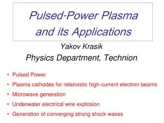
Pulsed-Power Plasma and its Applications. Pulsed Power Plasma cathodes for relativistic high-current electron beams Microwave generation Underwater electrical wire explosion Generation of converging strong shock waves. Yakov Krasik Physics Department, Technion. What is Pulsed Power ?.

E N D
Pulsed-Power Plasma and its Applications • Pulsed Power • Plasma cathodes for relativistic high-current electron beams • Microwave generation • Underwater electrical wire explosion • Generation of converging strong shock waves Yakov Krasik Physics Department, Technion
What is Pulsed Power ? Power 109-1014W, Energy 105-107eV Current 104-107A, Pulse duration 10-9-10-5 s • Slow storage of energy (100-2 s) • Compression stages (10-6 - 10-7 s) • Forming and Transmission Elements (10-8 s) • Load: electron and ion diodes, z-pinches, antenna • Product: pulsed power discharges, beams of charged particles, X-rays, neutron bursts, plasma heating, microwaves, laser beams, magnetic field compression.
Pulsed Power Applications • High-Power Bremsstrahlung Sources(Electron beams) • Dose ~ Ee2.8Ie(HERMES III: 20MeV, 700kA, 30ns 100 kRad at 500 cm2) • High Intensity Neutron Fluxes ( Ion beam 10131n0/pulse) • Strong Shock Wave Generation(electron and ion beams) • Pressure ~ Pb/(S); Pb ~ 1013 W/cm2 Pressure ~ 10Mbar • High-Power Microwaves(Microwave power 10 GW) • High-Power Pulsed Gaseous Lasers • Strengthening and Modification of Materials • Thin Film Preparation
כור היתוך (ריאקציה מיזוג גרעיני) טריטיום דאיטריום
Confinement Fusion 2H1 +3H14He2 (3.6 MeV)+1n0 (14 MeV) [Energy: 1 kg 1014 J] The volume rate of fusion reactions: Confinement time International Thermonuclear (Tokamak) Experimental Reactor: ITER [2015 (2021)] n 1014 cm-3; T 10 keV; 400 s; Pin = 40 MW; Pout = 500 MW (0.5 g D-T in 840 m3 volume) Plasma major radius: 6.2 m; Plasma minor radius: 2 m Plasma current – 15 MA; Average neutron flux: 0.5 MW/m2 Magnetic field at axis: 5.3 T Toroidal magnetic field energy – 41010 J
Inertial Confinement Fusion Confinement time: time it takes sound waves to travel across the plasma Adiabatic compression: Solid DT: 0.2g/cm3.Compression:104. R=0.1mm. Pressure:106bar. Energy: 106J. Power:1014W/cm2 Electron/Ion/Laser beams or soft x-rays rapidly heat the surface of the fusion target forming a surrounding plasma layer Ignition The fuel core reaches 104 of T-D density andignites at 10 keV Burn Thermonuclear burn spreads through the compressed T-D, yielding the input energy. Compression Target is compressed by plasma expansion • Electron Beams • Ion Beams • Laser Beams(NIF: Lawrence Livermore National Lab) • Soft X-rays (Z-pinch:Sandia National Lab)
Z-pinch USA, UK, France, Russia, Israel, Japan, China Soft X-ray radiation 2 MJ, 290 TW Hohlraum radiation temperature 200 eV Sandia National Laboratory 40mm Tungsten wire Array 240 5m wires
Z-pinch (Z-accelerator: upgrade to 60 MA) Achieved: X-ray output: 1.9 MJ, 280 TW Achieved: conversion efficiency: 15% Required X-ray output: 10MJ,1000TW D-T target energy: 1000 MJ Z-accelerator M. G. Haines, et al. Phys. Plasmas 7, 1672 (2000)
High-current electron beams Planar diode EA = EC Qi=Qe Iete = Iiti Ie = Ii(mi/me)1/2 • Alfven current:IA = 17bg [kA] • Space-charge-limited current:Is-ch= (mec3/2e)(g 2/3 - 1)3/2/[1+2ln(R/rb)] • Lawson current:IL = IAb2(b2+ f - 1)-1, f = (ni/ne)
High-current electron diode Example of closure of Anode-Cathode gap by plasma dac= 20mm, Ua= 180 kV, I = 2.5 kA. Frame 10 ns Potential distribution in the plasma prefilled diode
High current ion beams Planar bipolar diode: Ii = Ie(me/Mi)1/2 It is necessary to increase life-time of electrons in the anode-cathode gap Reflex systems Magnetically insulated ion diode PFBA II: Li-ion beam: Ei = 6MeV, Ii =1MA, t=25ns, W =1.4TW/cm2 Necessary for ignition - 5 TW/cm2
Flashover Plasma Carbon fiber cathode Formation of emission centers depends strongly on the growth rate of the electric field
Flashover Plasma(ferroelectric plasma cathodes) Plasma model Polarization Reversal model Light Emission (BaTiO3 cathode, e=1700) Frame 5 ns
Plasma Opening Switch • Anomalous fast magnetic field penetration • Classical diffusion time: Experiment: 10-8 - 10-6 s • Fast increase of the plasma resistivity:107-109W/s • Generation of high-current electron and ion beams
Anomalous fast magnetic field penetration • Electron Magnetohydrodynamics (Hall effect ) • Current channel:d >> (c/wpe)??? • Energy dissipation mechanism ???
Relativistic S-band magnetron Linear Induction Accelerator • The accelerator pulse: 450kV, 4kA, ~100ns. • The microwave pulse is 250 MW lasting ~70ns Typical voltage, current and MW waveforms Typical framing image (10ns) of the explosive plasma emission Purpose: • To increase efficiency of microwave generation to 40 % and to achieve microwave power of 400 MW • To achieve 1 GW microwave power in compressor with optimal coupling
Relativistic double gap vircator • The accelerator pulse: 550kV, 12kA, ~400ns. • The microwave pulse • is 200 MW, ~200ns • Waveforms of the voltage and current. (b) RF signal and its FFT. • (c) Diode impedance. (d). Radiation spectrum External view of the metal-dielectric, carbon fiber, and velvet cathodes (left-to-right). Purpose: • To avoid plasma formation at the surface of the cathode screen electrode • To increase duration of the microwave pulse up to 400 ns • To obtain microwave pulse with energy of 100 J (400 ns, 250 MW)
Underwater Electrical Wire Explosion 1 m wire 135 Leyden jars 1 kJ stored energy Earliest work on exploding wires was undertaken in Holland by Martinus van Marum in 1790 (http://chem.ch.huji.ac.il/history/marum.html)
Wire electrical explosion – a spiky change in the physical state of the metal as a result of intense energy input due to pulsed current with density >106 A/cm2 Flash Lamp, Laser Time Delay Generator HV Pulse Generator Mirror Streak or Framing Camera + CCD Current density: 106 – 1010A/cm2. Current pulse duration: 10-4 – 10-8 s. Power: 106 – 1013 W. Delivered Energy: 102 – 106 J Background medium: vacuum, gas, liquid Wire explosion in water Two frame (5 ns) images with 300 ns interval The wire Shock waves Discharge plasma channel
Basic Fundamental Research • Ultra-fast heating of metals: dT/dt > 10110K/s • Magnetic field: 107 G Energy density: 1011J/m3 Phase transitions: solid state liquid gas plasma Equations of State at extreme conditions (pressure: Mbar, temperature: 104 K) Pressure Density Temperature Conductivity Internal energy Thermal conductivity • Non-ideal plasma (high density, low temperature) Potential energy of Coulomb interaction Thermal energy Classical plasma Resistivity and thermal conductivity – differ strongly from the case of ideal plasma V. Fortov and I.T. Iakubov, The Physics of Non-Ideal Plasma ( World Scientific Publ., NJ, 2000)
Applications • High-power radiation sources (visible, UV range) : P >109 W • Lasers (1000 Ǻ) & Pumping of gaseous and ruby lasers • (intensity an order of magnitude greater than that obtained from Xe flash lamps) • Pulsed neutron source [CD2 or LiD wires: up to 10121n0/pulse: NRL (650kA, 100ns)] • Nano particles (1 – 100 nm) of different metals • Shock waves: underwater electrical wire explosion • High-current opening switch (high-voltage generator) • Powerful soft x-ray sources (Lebedev Physical Institute, Cornell University) Current : 300 kA, 100 ns • Point-like source 10 m • Time duration10 ps – 200 ps • Soft x-ray energy 2 – 15 keV • Hard x-ray energy 25 - 80 keV
High-current and high-voltage generators (>106V, 104A, 10-7s)
Main Obstacles in Electrical Wire Explosion in vacuum/gas Shunting of the Discharge. The best energy deposition in vacuum recently achieved by Sarkisov et al.* was 20 times the atomization enthalpy. 2. Fast plasma expansion (107 cm/s) in vacuum limits energy density input 3. Radiation cooling in vacuum wire explosion limits plasma temperature 4. Fast growing plasma instabilities and charged particle emission
Underwater Electrical Wire Explosion (UEWE) • High Density Non-Ideal Plasma • Ultra High Pressure at the axis of Converging Cylindrical Shock Wave produced by Underwater Electrical Wire Array Explosion Advantages of the Underwater Electrical Wire Explosion Shunting of the discharge is prevented due to: High breakdown voltage of the water medium (>300 kV/cm). High pressure of the adjacent water layer (>10 kBar) increases breakdown voltage. Increase in the temperature of the wire plasma is achieved by: High resistance of the water to compression limits the wire expansion and leads to the increase in the current density. Substantial decrease in the energy loss to the shunting channel and to radiation (water “bath” effect).
Microsecond Timescale Generator • Stored energy: W≤ 4.5 kJ • Voltage: V≤ 30 kV • Peak current: I≤400 kA • Capacitance: C =10 μF • Self-inductance:L=60 nH • Power: Nanosecond Timescale Generator • Stored energy: • Voltage: • Peak current: • Wave impedance: • Power: MA Generator(with Institute of High Current Electronics, RAS) • Stored energy: 9.5 kJ • Current amplitude: 900 kA • Rise time: 300 ns • Power: 60 GW
Diagnostics Tools • Electrical probes: voltage & current monitors • Electro – mechanical pressure gauges • Optical: Schlieren & Shearing Interferometry • Fast streak and frame shadow imaging • Fast photodiodes & narrow band interference filters • Visible range spectroscopy
Microsecond timescale UEWE Nanosecond timescale UEWE Cu Wire 510µm, 85mm in length Cu Wire 100µm, 50mm in length Electric measurement & Hydrodynamic calculation • μsec nsec • Stored Energy [kJ] ~ 7.0 ~ 0.7 • Current Rise Rate [A/s] ~ 10 10 ~ 10 12 • Maximal Electrical Input Power [GW] ~ 2.0 ~ 6.0 • Maximal Energy Deposition[eV/atom] ~ 10 ~ 60-200 • Maximal Generated SW Pressure [kBar]~10 ~100 • Maximal DC Temperature [eV]~ 1.0~7.0 A. Grinenko, Ya. E. Krasik, S. Efimov, A. Fedotov, V. Tz. Gurovich and V.I. Oreshkin, Physics of Plasmas 13, 042701 (2006).
Water Vaporization by the Heating Wire The phase state trajectoryof a < 5 μm water layer for different heating rates No evidence of shunting channel observed !!! Power < 6 GW, Energy < 0.7 kJ T t T t2 • A thin water layer (~ 1-5 µm) adjacent to the heating wire remains in the liquid state during all the heating processfor heating rates: Tc/0.5μs 109 oC/s (Tc=420oC is the critical temperature of the water). The phase trajectory lies above the saturation curve during the heating process NO BOILING
Water “Bath” Effect • For I3 MA wire explosion, the >13.5 eV radiation from the wire ionizes the water. This causes currentredistribution between the discharge channel and the water. • The energy lost by the discharge channel to the water plasma channel is re-absorbed due to radiation heat transfer from the water-plasma to the discharge channel Maximum fraction of the shifted current is 30% Time dependence of thermal energy and radiated energy of the DC. Negative values of radiated energy correspond to absorption.
Energy density scaling The deposited energy per unit length is proportional to Π(power rate per unit length) Shearing interferometry combined with shadow imaging, hydrodynamic and optical simulations allows estimation of the efficiency of the energy transfer to the generated SW as ~ 15%.
UEWE: Radiation Short pulse emission (300 ns) (during the wire explosion from the wire surface) Spectrally resolved radiation Long pulse emission (100 μs) is aresult of a growth of emitting area due to creation of micro-particles and their relatively long cooling
MHD Calculations Mass conservation Momentum conservation Energy conservation Maxwell equations Ohm law Equations of state Transport parameters
MHD Calculations Experimental & MHD calculation results of the explosion of Cu (L=100mm, Ø100μm) wire Solid curves – experimental results Dashed curves – MHD calculation. Time [ns] Surface temperature ~ 2 eV On axis pressure ~ 400 kBar
Implosion Due to the cumulation effect of the converging SWit is possible to achieve ultra-high pressure at the axis of implosion • Self-similarity problem • R t • In the case of diverging SW (total energy of the • explosion is conserved in the volume limited by • the SW) the parameter can be determined using • dimensional analysis of physical parameters • In the case of implosion the energy in the volume • between the SW and the exploding liner is not • conserved: thus cannot be determined without • hydro-dynamic numerical simulations. Parametric Similarity Cylindrical Geometry Initial energy α ~ 0.6 - spherical implosion α ~ 0.75 - cylindrical implosion Initial radius • A. Grinenko, V. Gurovich,Ya. Krasik, Phys. Plasmas 14, 012701 (2007). V. Gurovich, A. Grinenko, Ya. Krasik, PRL 99, 124503 (2007).
Implosion – Experimental Setup Imploding array Implosion wave Target Streak image of the implosion with a cylindrical wire array 40ty 50m dia Cu-wire array Ya. E. Krasik, A. Sayapin, A Grinenko,and V. Tz. Gurovich,Phys. Rev. E 73, 057301 (2006).
Cylindrical SW Implosion 40 Cu wires (Ø0.1mm) array (R0 = 2.5 mm) Damping of initial non–uniformity of SW front is evident in 2D simulations Landau & Stanukovich: • The pressure is estimated as ~400 50 kbar at r = 0.1 mm (4.5 kJ microsecond setup) • Initial SW pressure generated by the wire explosion is 10kbar.
The calculated DT reaction yield for various implosion parameters: • Rsh [mm] Rt = [mm] ET = [kJ] Reaction Yield x1013 • 5.0 0.25 31.2 4.23 • (2) 5.0 0.25 10.8 7.88 • (3) 7.5 0.50 36.5 14.7 • (4) 5.0 0.50 10.2 1.05 D-T Gas Mixture Target Ignition • The Model Includes: • Bremsstrahlung radiation losses • NO molecular, electron or • radiative heat transfer • NO instabilities • NO energy transfer by α particles