Download
1 / 6
0 likes | 45 Views
Suggest:For more complete manuals. Please go to the home page.<br><br>https://www.ebooklibonline.com

E N D
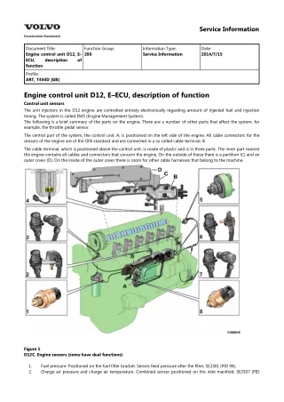
Service Information Document Title: Engine control unit D12, E– ECU, description function Function Group: 200 Information Type: Service Information Date: 2014/7/15 of Profile: ART, T450D [GB] Engine control unit D12, E–ECU, description of function Control unit sensors The unit injectors in the D12 engine are controlled entirely electronically regarding amount of injected fuel and injection timing. The system is called EMS (Engine Management System). The following is a brief summary of the parts on the engine. There are a number of other parts that affect the system, for example, the throttle pedal sensor. The central part of the system, the control unit, A, is positioned on the left side of the engine. All cable connectors for the sensors of the engine are of the DIN standard and are connected in a so called cable terminal, B. The cable terminal, which is positioned above the control unit, is made of plastic and is in three parts. The inner part nearest the engine contains all cables and connectors that concern the engine. On the outside of these there is a partition (C) and an outer cover (D). On the inside of the outer cover there is room for other cable harnesses that belong to the machine. Figure 1 D12C. Engine sensors (some have dual functions) 1. 2. Fuel pressure. Positioned on the fuel filter bracket. Senses feed pressure after the filter, SE2301 (PID 94). Charge air pressure and charge air temperature. Combined sensor positioned on the inlet manifold, SE2507 (PID
105), SE2508 (PID 102). Camshaft position. Positioned near the top of the cylinder head at the front, SE2703 (SID 21). Coolant level. Positioned in the expansion tank, SE2603 (PID 111). Air pressure and air temperature. Combined sensor, positioned on the connecting pipe between the air filter and the turbocharger, SE2501 (PID 172), SE2502 (PID 107). Coolant temperature. Positioned in the rear end of the cylinder head, SE2606 (PID 110). Flywheel position and rotational speed. Positioned in the flywheel housing, SE2701 (SID 22). Oil pressure and oil temperature. Combined sensor positioned in the lubrication system main duct in the cylinder block, SE2202 (PID 175), SE2203 (PID 100). 3. 4. 5. 6. 7. 8. Figure 2 D12D Engine sensors (some have dual functions) 1. 2. 3. 4. 5. 6. 7. 8. 9. Sensor for coolant level, SE2603 Sensor for coolant temperature, SE2606 Sensor for charge air pressure/temperature, SE2507/SE2508 Tachometer sensor, flywheel, SE2701 Sensor for oil level/temperature, SE2205/SE2202 Sensor for crankcase pressure, SE2509 Sensor for oil pressure, SE2203 Camshaft sensor, engine position, SE2703 Sensor for air pressure/temperature, SE2501/SE2502 Sensor for feed pressure, fuel, SE2301 Sensor for water indicator, SE2302 10. 11.
Service Information Document Title: E–ECU D12, Functions Function Group: 200 Information Type: Service Information Date: 2014/7/15 Profile: ART, T450D [GB] E–ECU D12, Functions Fuel amounts, unit injectors Figure 1 Unit injector "Bosch" Figure 2 Unit injector "Delphi" Exhaust brake Applies only to machine equipped with engine D12C
Suggest: If the above button click is invalid. Please download this document first, and then click the above link to download the complete manual. Thank you so much for reading
Figure 10 V1022272 18. The condition for reading off correct compression pressure is that the valve clearance is correct. See: 214 Valves, adjusting 19. Connect compression gauge 9988539 to adapter 9998248 on the first cylinder. Run the engine with the starter motor until the needle on the compression gauge stops (max.compression value). Repeat the procedure for the other cylinders. On a new engine, the compression pressure is normally approx. 30 bar. Low compression pressure on all cylinders indicates worn cylinder liners and/or worn piston rings. When comparing the compression pressure in the different cylinders and you detect any cylinder with lower pressure, this may be due to leaking valves, cracked piston rings, worn cylinder liner, or leaking cylinder head gasket. In case of this, Engine, overhauling should be done. Uniformity between the cylinders' compression pressure is the most important and should not exceed 20%. NOTE! The parking brake must be applied when cranking the engine with the starter motor. NOTE! Do not run the starter motor for longer than 10 seconds at a time, with intervals of 60 seconds. Figure 11 V1022273 Assembling 20. Remove the compression gauge 9998539 and adapters 9998248. 21. Loosen the bolts for the rocker arm shaft evenly across the entire shaft, so that the rocker arm shaft is not subjected to transverse loading. Remove the bolts and install lifting tool 9990185 and 88880003. Carefully lift away the rocker arm shaft.
Figure 12 V1039942 22. Install the unit injectors with new O-rings and centre the unit injectors between the valve springs. Install the attaching yokes. Tightening torque: see 230 Tightening torque, fuel system Figure 13 23. Lift the rocker arm shaft into place with 9990185. Make sure that the guide pins fit in the support bearing for the