Download

1 / 56
2.08k likes | 7.67k Views
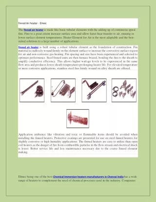
Flue Gas system Air pre Heater. www.powerpointpresentationon.blogspot.com. Presentation Plan. Air heaters Types of air heaters Materials Used Sealing arrangement for air heaters Air heater Performance Performance tests. BYPASS SEAL. RADIAL SEAL. HOT END. AXIAL SEAL. HOT INTERMEDIATE.

E N D
Flue Gas system Air pre Heater www.powerpointpresentationon.blogspot.com
Presentation Plan • Air heaters • Types of air heaters • Materials Used • Sealing arrangement for air heaters • Air heater Performance • Performance tests
BYPASS SEAL RADIAL SEAL HOT END AXIAL SEAL HOT INTERMEDIATE COLD END AIR PRE HEATER APH is the last heat exchanger in the boiler flue gas circuit. To achieve maximum boiler efficiency maximum possible useful heat must be removed from the gas before it leaves the APH. However certain minimum temperature has to be maintained in the flue gas to prevent cold end corrosion
Air Pre-Heater-functions • An air pre-heater heats the combustion air where it is economically feasible. • The pre-heating helps the following: • Igniting the fuel. • Improving combustion. • Drying the pulverized coal in pulverizer. • Reducing the stack gas temperature and increasing the boiler efficiency. • There are three types of air heaters: • Recuperative • Rotary regenerative • Heat pipe
Advantages by use of APH • Stability of Combustion is improved by use of hot air. • Intensified and improved combustion. • Permitting to burn poor quality coal. • High heat transfer rate in the furnace and hence lesser heat transfer area requirement. • Less un-burnt fuel particle in flue gas thus combustion and both r efficiency is improved. • Intensified combustion permits faster load variation and fluctuation. • In the case of pulverised coal combustion, hot air can be used for heating the coal as well as for transporting the pulverised coal to burners. • This being a non-pressure part will not warrant shut-down of unit due to corrosion of heat transfer surface which is inherent with lowering of flue gas temperature.
Types Of Air Preheater • Recuperative • Regenerative • Plate type Airheater • Steam Air Preheater • Langsdorm type • Rothemuhle type • Tri sector Air Heater
Design Parameters • Tubes are generally arranged in staggered pattern. • Steel tubes of Dia: 37 – 63 mm. • Transverse pitch: S1/d = 1.5 – 1.9 • Longitudinal pitch: S2/d = 1.0 – 1.2 • The height of air chamber:1.4 – 4.5 m. • Gas and Air flow velocity : 10 – 16 m/s. • Plate Recuperators: • Instead of tube, parallel plates are used. • The gas passage is 12 – 16 mm wide. • The air passage is 12 mm wide.
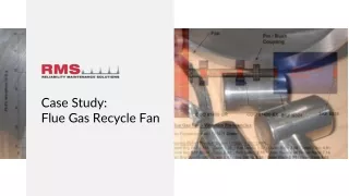
BYPASS SEAL RADIAL SEAL HOT END AXIAL SEAL HOT INTERMEDIATE COLD END Regenerative air pre heater
Rotary Plate (Regenerative) type Pre-Heater • Rotates with a low speed : 0.75 rpm. • Weight : 500 tons. • This consists of : rotor, sealing apparatus, shell etc. • Rotor is divided into 12 or 24 sections and 12 or 24 radial divisions. • Each sector is divided into several trapezoidal sections with transverse division plates. • Heat storage pales are placed in these sections.
The Material used in APH for heat storage • Material used Cold end in the basket is a special type of steel (corten steel (trade name)) which has high resistance to the low temperature sulphur corrosion, thus prolonging operational life. • In the hot end mild steels are used • The optimal geometric shape is usually corrugated and sizes are determined based on design modelling and experimental data. The turbulence of air and gas flow through the package increases the heat transfer rate.
Stationary-Plate Type Air Pre-Heater • The heat storage elements are static but the air/gas flow section rotates. • The storage plates are placed in the stator.
Heating Elements • Hot End Baskets • Hot Intermediate Baskets • Cold End Baskets
TYPES OF SEALS • RADIAL SEAL (HE & CE) • AXIAL SEAL • CIRCUMFERENTIAL SEAL • ROTOR POST SEAL • SECTOR PLATE STATIC SEAL
PERCENTAGE AIR LEAKAGE OF TOATAL LEAKAGES • HE Radial seal leakage - 62.21% • CE Radial seal leakage - 11.98% • Axial seal leakage - 08.78% • By pass or circumferential seal leakage - 0.87% • Center post seal leakage - 3.17% • _______________________________________________ • Total percentage = 87.01% • Entrapped leakage = 12.99% • TOTAL = 100%
RADAIAL SEALS & SECTOR PLATE • RADIAL SEALS AND SECTOR PLATES ARE LOCATED AT THE HOT AND COLD ENDS OF THE AIR PREHEATER. THE RADIAL SEALS ARE ATTACHED TO THE DIAPHRAGMS, WHICH SEPARATE THE INDIVIDUAL ROTOR COMPARTMENT. • PURPOSE: - THE PURPOSE OF RADIAL SEALS IS TO REDUCE THE AREA AVAILABLE FOR LEAKAGE FROM THE AIR TO THE GAS SIDE BETWEEN THE DIAPHRAGM AND THE SECTOR PLATE
AXIAL SEALS AND SEALING PLATES • AXIAL SEALS MINIMIZE LEAKAGE PASSING RADIALLY AROUND THE ROTOR SHELL. THE AXIAL SEALS ARE MOUNTED ON THE OUT SIDE OF THE ROTOR SHELL AND SEAL AGAINST THE AXIAL SEAL PLATES MOUNTED ON THE AIR PREHEATER HOUSING.
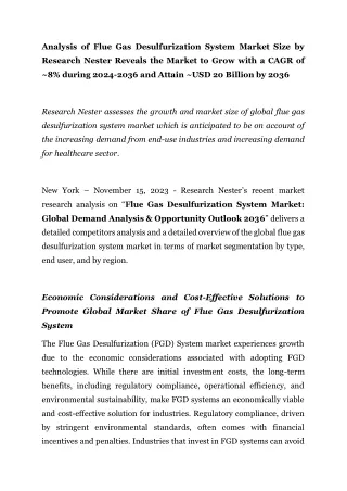
AXIAL SEAL DIAPHRAGM COG RIM PIN
AXIAL SEALPLATE AXIAL SEAL INSPECTION DOOR TURN-BUCKLE ADJUSTABLE BOLT JACK BOLT
Axial Seal Arrangement • Curved axial sector plate adjustable from outside • Seal strips are attached to the rotor. • The thickness of seal strips : • 6 MM straight strips in Russian. • 2.5 mm thick and bend backward in BHEL. BHEL APH has better accessibility of axial seal adjustment as compared to Russian design
CIRCUMFERENTIAL SEALS • THE CIRCUMFERENTIAL SEALS PREVENT AIR AND GAS FROM BYPASSING THE HEATING SURFACE THROUGH THE SPACE BETWEEN THE ROTOR AND THE HOUSING SHELL. THEY ALSO PREVENT AIR AND GAS FROM FLOWING AXIALLY AROUND THE ROTOR.
CIRCUMFERENTIAL SEAL-RUSSIAN CIRCUMFERENTIAL SEAL H.E. DIAPHRAGM 2.5MM RADIAL SEAL H.E. ROTOR FLANGE
ROTOR FLANGE AXIAL SEAL CIRCUMFERENTIAL SEAL ADJUSTABLE BOLT
CIRCUMFERENTIAL SEALS ACTUATING MECHANISM-RUSSIAN Actuating Bolt
ROTOR POST SEALS • ROTOR POST SEALS PREVENT LEAKAGE BETWEEN THE ENDS OF THE ROTOR POST AND THE AIR PREHEATER HOUSING. • THE STATIC SEALS PREVENT LEAKAGE BETWEEN THE HOT & COLD END SECTOR PLATES AND THE HOT AND COLD END CENTER SECTIONS.
SECTOR PLATE STATIC SEAL HE ROTOR POST SEAL
DIAPHRAGM CE ROTOR POST SEAL
THICKNESS OF RADIAL SEAL STRIPS • RUSSIAN MODEL : 6 MM • BHEL DESIGN : 2.5 MM • SOFT SEAL : 0.1 MM
FLEXIBLE / SOFT SEALS • THE FLEXIBLE SEALS WAS DEVELOPED TO REDUCE NORMAL LEAKAGE CAUSED BY THE THERMAL EXPANSION OF THE ROTOR WHILE THE UNIT IS OPERTAING. THE ROTOR EXPANSION OPENS UP AREAS OF DIRECT AIR TO GAS LEAKAGE THAT CAN BE GREATLY REDUCED BY INSTALLING FLEXIBLE SEALS. • MERIT : - SOFT SEAL IS SET TO A NEGATIVE CLEARANCE IN COLD CONDITION, AND WHICH WILL EXTEND IN THE HOT CONDITION TO OPERATE AS A STANDARD PROXIMITY SEAL. • DEMERIT : - SINCE THIS IS AN INTERFERENCE OR CONTACT SEAL, THE WEAR LIFE IS VERY LOW.
COST OF SOFT SEALS • RADIAL SOFT SEAL HE/ SET :- 1 LAC • RADIAL SOFT SEAL CE/ SET :- 0.95 LAC • AXIAL SOFT SEAL/ SET :- 0.4 LAC
BY PASS SEAL RUSSIAN BY PASS SEAL RUSSIAN
APH PERFORMANCE • Boiler efficiency decreases generally on account of APH performance degradation. This also affects ESP, ID & FD fan loadings & at times unit capability • Factors affecting APH performance • Excess air level / No of Mills in service • Primary Air to Secondary Air ratio • Moisture in coal/ Air ingress level • Performance of upstream ash evacuation system • Procedure for cleaning, soot blowing & regular maintenance etc.
APH PERFORMANCE • Higher than expected leakage would decrease the flue gas exit temperature, resulting in false sense of improved working. • Higher inlet flue gas temperature is rather rare, but this could be one reason for high exit temperature. • Optimum flue gas temperature is required for effective ESP performance • Unequal temperature at air heater exit should be investigated.
FLUE GAS EXIT TEMP AT APH OUTLET • FLUE GAS TEMP AT AH OUTLET IS INDICATIVE OF HEAT LEAVING THE UNIT .THIS IS LOWERED ON ACCOUNT OF AH LEAKAGES. • FGET TO BE MEASURED AT A LOCATION SLIGHTLY AWAY FROM AIR HEATERS. • NO OF TEMPERATURE SENSOR PROVIDED SHOULD COVER THE DUCT ADEQUATELY. • CORRECTED TEMP SHOULD BE USED FOR COMPARISION.
CO2 measurement is preferred due to high absolute values; In case of any measurement errors, the resultant influence on leakage calculation is small. • Air Leakage Weight of air passing from air side to gas side; This leakage is assumed to occur entirely between air inlet and gas outlet • Hot End / Cold End / Entrained Leakage • Calculation Empirical relationship using the change in concentration of O2 or CO2 in the flue gas • = CO2in - CO2out * 0.9 * 100 • CO2out • = O2out - O2in * 0.9 * 100 = 5.7 – 2.8 * 90 • (21- O2out) (21-5.7) • = 17.1 %
PERFORMANCE DEGRADATION OF APH • Seal Leakage • Erosion • Corrosion • High Press Drop Across APH • APH Fire
APH Performance Test • APH Leakage • Gas Side Efficiency • X-Ratio