Download
1 / 37
370 likes | 467 Views
Basic Control Theory and Its Application in AMB Systems. Zongli Lin University of Virginia. Representation of a Plant. Representation of a Plant. Representation of a Plant. Example 4. Principles of Feedback. Tracking Requirement. Disturbance Rejection.

E N D
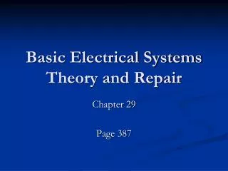
Basic Control Theory and Its Application in AMB Systems Zongli Lin University of Virginia
Representation of a Plant Example 4
Principles of Feedback • Tracking Requirement
Disturbance Rejection (change in load, aero or mechanical forces, etc) Disturbance Rejection Requirement
Sensitivity Sensitivity to plant uncertainties
k=256 High-Gain Causes Instability • High Gain Instability
Limitations of Constant Feedback • Constant feedback is often insufficient
Integral Action • Use of integral action for zero steady state error (r(t)=1(t), e.g., raise rotor vertical position) K(s) = k K(s) = k/s Observation: Large k causes actuator saturation
Differential Action • Use of differential action for closed loop stability • K(s)=k • K(s)=kP+kDs • In general: PID control
Example • Decentralized PI/PD position control of active magnetic bearings Above: cross section of the studied active magnetic bearing system Right: cross section of the studied radial magnetic bearing Reference: B. Polajzer, J. Ritonja, G. Stumberger, D. Dolinar, and J. P. Lecointe, “Decentralized PI/PD position control for active magnetic bearings”, Electrical Engineering, vol. 89, pp. 53-59, 2006.
Stabilization • Stabilization: PD control
Steady State Error • Steady state error reduction: PI Control (e.g., to avoid mechanical contact) • PI/PD control configuration
PD/PD vs PID Control • PD: Choice of Kd and Td is ad hoc. • PI: Choice of Ki and Tiis ad hoc. • PID: Choice of 3 parameters even harder
Increased steady state accuracy Increased PM Increased PM Lag and Lead Compensation Compensation objectives:
Lag and Lead Compensation Phase lag compensator
Lag and Lead Compensation Phase lead compensator
An LP Centrifugal Compressor (ISO 14839) Two mass symmetric model of the rotor in an LP centrifugal compressor
An LP Centrifugal Compressor (ISO 14839) Mathematical model
An LP Centrifugal Compressor (ISO 14839) Transfer functions:
An LP Centrifugal Compressor (ISO 14839) Decentralized control design Open-loop poles: Stabilization requires a large increase in the phase
An LP Centrifugal Compressor (ISO 14839) Three PD controllers (to approximate 3 lead compensators)
An LP Centrifugal Compressor (ISO 14839) Compensated bode plots Closed-loop poles:
An LP Centrifugal Compressor (ISO 14839) Closed-loop poles in the presence of aero cross coupling:
Challenges in Control of AMB Systems PID Control and lead/lag compensators • Choice of parameters • Coupling between channels • Flexible rotor leads to higher order plant model
A More Realistic Design Example Parameter varying (gyroscopic effects): Potential approach: LPV (Linear Parameter Varying) Approach • Based on gain scheduling • Conservative in performance
A More Realistic Design Example Piecewise • Design several controllers at different speeds; • Each controllers robust in a speed range; • Switch between controllers as the speed varies; • Bumpless switching is the key
A More Realistic Design Example Control Switching Conditions for a Bumpless Transfer:
A More Realistic Design Example Bumpless Transfer Build an observer that estimates the off line controller state from the on line controller output Use the estimated state as the initial state at time of switching As a result,
A More Realistic Design Example Piecewise controller design • Controller 1 at nominal speed 10,000 rpm • Controller 2 at nominal speed 15,000 rpm • Each covers +/- 4000 rpm • 48th order controllers
A More Realistic Design Example Transfer at 12,000 rpm (upper bearing, x direction)
A More Realistic Design Example Transfer at 12,000 rpm (upper bearing, y direction)
More Challenges in Control of AMB Systems Nonlinearity of the AMB input-output characteristics