Download
1 / 21
250 likes | 553 Views
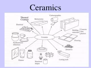
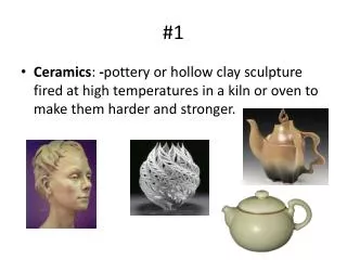
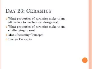
Day 23: Ceramics. What properties of ceramics make them attractive to mechanical designers? What properties of ceramics make them challenging to use? Manufacturing Concepts Design Concepts. Manufacturing Ceramics.

E N D
Day 23: Ceramics • What properties of ceramics make them attractive to mechanical designers? • What properties of ceramics make them challenging to use? • Manufacturing Concepts • Design Concepts
Manufacturing Ceramics • The following methods are used to shape the ceramics. Please not that (wetted) powder is key.
Sintering • This is a process in which the small chunks of powder loose their identity, as the whole (porous) part is bonded. Temperature and often pressure are needed. Shrinkage has to be understood.
Die Pressing (Uniaxial Pressing) • Most common and rapid for small ceramic components where speed of manufacture means more than strength and uniformity. • Pressure, and densification is variable through the mold. The object will have varying properties, and maybe differential shrinkage on sintering. • Simple shapes only. • Hot pressing is a combination of sintering and die-pressing happening at once.
Isotactic Pressing • Pressure transmitted to the powder from a compressed fluid. • More uniformity, less porosity • An elastomer (rubber mold) serves as the interface. • Slower rate of production. • Best for cylindrical shapes, eg. Spark plug. Hot isotact pressing (HIP) combines sintering and isotactic pressing.
Extrusion • We add a plasticizing agent, which is later cooked away during sintering.
Slip Casting • Make a slurry by adding liquid to the powder. • Pour into a porous mold. • Fluid is absorbed by the mold leaving a drier layer of powder along the walls. • Pour off remaining slurry, slip. Opening the mold reveals the thin-walled object. • Ready to be sintered.
Injection Molding • This method holds the most promise for mass production of complex shapes as evidenced by its use in producing ceramic turbocharger rotors. A combination of 60-70% powder mixed with an organic binder to provide flow is injected into a mold. Prior to sintering, burnout of the binder must be done. Current restrictions include small wall thickness. Because of the cost of equipment, this is only cost-effective for large volumes, and for simple shapes, the dry pressing methods are more cost-effective.
Reaction Bonding • A solid powder and a gas or liquid react during sintering to densify and bond. • In Reaction Bonded Silicon Nitride, silicon powder is fired in the presence of high pressure nitrogen gas, and the reaction forms Si3N4. • Advantage: very low shrinkage. • Disadvantage: high porosity and lower strengths.
More Reaction Bonding • Reaction bonded silicon carbide, RBSC, is made by infiltrating liquid silicon into a compact of carbon and silicon carbide. The Si reacts with the carbon to form SiC which then bonds with the original SiC particles. Pores are filled with liquid Si. Consequently, high temperature strength falls off at silicon's melting temperature. Dimensional changes with RBSC can be less than 1%. One interesting variation is to use carbon fibers rather than carbon particles.
Summary of Materials • Hot-pressed silicon nitride (HPSN) has the strongest specific strength (strength/density) at 600oC of any material. It has excellent thermal shock resistance. • Sintered silicon nitride (SSN) has high strength and can be formed into complex shapes. • Reaction-bonded silicon nitride (RSBN) can be formed into complex shapes with no firing shrinkage. • Hot-pressed silicon carbide (HPSC) is the strongest of the silicon carbide family and maintains strength to very high temperatures (1500oC). • Sintered silicon carbide (SSC) has high temperature capability and can be formed into complex shapes • Reaction-bonded silicon carbide (RSBC) can be formed into complex shapes and has high thermal conductivity. • Partially stabilized zirconia (PSZ) is a good insulator and has high strength and toughness. It has thermal expansion close to iron, facilitating shrink fit attachments.
Designing With Ceramic Materials • Deterministic design, is where we predict a definite “yes” or “no” as to failure based on comparing strength data with loads through calculations. • Does not work for ceramics, since strength data is so scattered. • We use a process called probabilistic design. We predict a probability of failure in the part given its material, geometry and loading.
Probability of Failure • We can assume that lots of testing was done on a ductile material. Stress between 0 and 300 MPa • We plot a histogram of the number of failures which occur at each level of stress. Get Bell Curve – Normal Distribution
Weibull Distribution • Now try a brittle ceramic. We find that the normal distribution or bell curve does not describe the probability of failure. Which looks like
Weibull Statistics • The actual data shows a tilt towards failure early on. Probability of early failures a lot more. This is kind of expected with brittle materials. • Weibull had the idea of describing this kind of thing with a probability distribution function that looked like: s0 is a scale parameter. m is the Weibull modulus
Cumulative Distribution Function -- Weibull • Given the above, we can find the probability of failure for all stresses below a given one. We do this by integrating. Example given in Maple of how this works.
Size is Important! • Suppose we have a chain of n links. For a single link, let F(s) be the probability of failure at a stress below and up to s. • Probability of survival at all stress up to s is 1- F(s) • Then the probability of failure of the chain of n links up to s is Fn(s) = 1 – (1 – F(s) )n. • Say we had a “chain” made out of n blocks of ceramic characterized by m and s0.
Size Effects We return to the Maple worksheet to see how the size increase has changed our CDF. It’s not pretty.
It’s Not That Simple! • Here we have been dealing with a unit volume or a chain of unit volumes in a state of uniaxial tension. • Practical designs will experience different volumes with various distributions of multiaxial stress. • Computational methods are used. CARES/Life is a program which takes finite element analysis of the component and calculates the overall probability of failure.
Proof Testing • Here the idea is to cut of the tail of the distribution by testing all parts prior to delivery. • This is expensive, but is sometimes done. • Problem: damage is cumulative. Proof testing can lead to damage that would shorten the life of the part.
Quick Review • Design to a minimum safe value is not possible! • We must design to an accepted probability of failure. • Weibull statistics is used instead of normal statistics in fitting data and computing probabilities. • The Weibull modulus indicates the extent to which the strength data is scattered. Want it as high as possible. • The size of the object being designed must be accounted for. Designs that work for small components won’t work for large.