Induction Generators
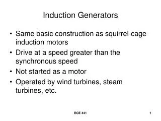
Induction Generators. Same basic construction as squirrel-cage induction motors Drive at a speed greater than the synchronous speed Not started as a motor Operated by wind turbines, steam turbines, etc. Motor – to – Generator Transition. Typical setup for induction-generator operation.


Induction Generators
E N D
Presentation Transcript
Induction Generators • Same basic construction as squirrel-cage induction motors • Drive at a speed greater than the synchronous speed • Not started as a motor • Operated by wind turbines, steam turbines, etc. ECE 441
Typical setup for induction-generator operation Initially, the turbine valve is closed 2 - Motor started at full voltage by closing the breaker 1 - Motor shaft coupled to a steam turbine 3 –Motor drives the turbine at less than synchronous speed ECE 441
Operation as an Induction-Generator continued Gradually open the turbine valve, causing a buildup of turbine torque, adding to the motor torque, resulting in an increase in rotor speed. ECE 441
When the speed approaches synchronous speed, the slip = 0, Rs/s becomes infinite, rotor current Ir = 0, and no motor torque is developed. (The motor is neither a motor or a generator – it is “floating” on the bus. The only stator current is the exciting current to supply the rotating magnetic field and the iron losses. ECE 441
The speed of the rotating flux is independent of the rotor speed – only a function of the number of poles and the frequency of the applied voltage. Increasing the rotor speed above the synchronous speed causes the slip [(ns – nr)/ns] to become negative! The gap power, Pgap = Prcl/s becomes negative, now supplying power to the system! ECE 441
Air – gap Power vs. rotor speed ECE 441
The interaction of the magnetic flux of the stator and the magnetic flux of the rotor produce a “countertorque” that opposes the driving torque of the prime mover. Increasing the speed of the rotor increases the countertorque and the power delivered to the system by the generator. The maximum value of the countertorque is called the “pushover” torque. ECE 441
Increasing the speed of the prime mover beyond the pushover point causes the power output to decrease. The countertorque decreases and the speed increases. This also occurs if the generator is loaded and the breaker is tripped. Motors used in these applications must be able to withstand overspeeds without mechanical injury. See Table 5.11, page 223. ECE 441
Table 5.11 page 223 ECE 441
Example 5.17 • A three-phase, six-pole, 460-V, 60-hZ, Induction motor rated at 15-hp, 1182 r/min, is driven by a turbine at 1215 r/min. 2The equivalent circuit is shown and the motor parameters (in Ohms) are: • R1 = 0.200 R2 = 0.250 Rfe = 317 • X1 = 1.20 X2 = 1.29 XM = 42.0 ECE 441
Example 5.17 continued • Determine the active power that the motor, driven as an induction generator, delivers to the system. ECE 441
Example 5.17 continued ECE 441
Example 5.17 continued ECE 441