Advanced Cryogenic Dynamic Modelling and Simulation Techniques at CERN
This presentation by Enrique Blanco (BE-ICS-AP) dives into the intricacies of dynamic process simulation applied to cryogenics at CERN. It covers essential topics, including the definition and importance of dynamic simulation, its application in cryogenic systems, and practical implementations at CERN. Key tools discussed include CRYOLIB and PROCOS, which facilitate the modeling of cryogenic processes. Moreover, the presentation illustrates simulations employed for CERN's cryogenic installations like the CMS and Central Helium Liquefier, providing insight into their operations and control strategies.

Advanced Cryogenic Dynamic Modelling and Simulation Techniques at CERN
E N D
Presentation Transcript
Cryogenic Dynamic Modelling and Simulation at CERN Presented by Enrique Blanco (BE-ICS-AP) on the original presentation made by Benjamin Bradu (TE-CRG-OP)
Contents • Introduction • What is dynamic process simulation ? • Why using it for cryogenics ? • How does it works ? • CERN approach • What do we do at CERN ? • CRYOLIB • PROCOS • Application to CERN cryogenic systems • CMS • CERN Central Helium Liquefier • LHC refrigerators (4.5 K and 1.8 K) • QRL • Beam Screens • Summary
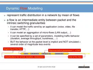
What is dynamic process simulation ? ≠ CFD simulation (different objectives, different techniques) • Simulation = mimic the reality in a computer • Need to model your system first ! • Dynamic = evolution over time • Applied on cryogenic processes: • Macroscopic modelling from a process point of view (0D/1D) • Use of an object-oriented modelling approach • Active equipment: valves, heaters, turbines, etc. • Passive equipment: pipes, HX, phase separators, etc. • Simulate all pressures, temperatures, mass flows over a cryogenic installation
EmpresariosAgrupados Document reference
EcosimPro (Libraries) Document reference
EcosimPro (Graphical design) Document reference
EcosimPro (Interfaces) Document reference
EcosimPro (Libraries)https://www.ecosimpro.com/products/ Document reference
Why using it for cryogenics ? • Train operators / Design Engineering • Safe training with no risk on the process • Simulate failure scenarios (e.g turbine or compressor trips) • Simulate occasional events (e.g. cooldown phases) • Validate new control strategies • No disturbance on the process • Fair comparison between strategies • Time saving • Perform virtual commissioning • Debug safely the control programs • Fast validation of complex starting/stopping sequences • Commissioning control systems offline • Reduce commissioning time with the real plant
How does it works ? Model each cryo component individually + fluid properties Build your complete model by assembling elementary components + Parametrize each component with your specifications (pipe diameter, valve size, etc.) Include basic control in model OR: couple it to real control system Define boundary conditions over time Simulate
What do we do at CERN ? • Modelling and simulation software • EcosimPro (EmpresariosAgrupados) • Cryogenic Library • CRYOLIB (see next slide) • Coupling with control system • Stand Alone simulation in EcosimPro with simplified control • PROCOS: Process and Control system coupling
CRYOLIB • CRYOLIB: a commercial library for modelling and simulation of cryogenic processes with EcosimPro. • History • 2001: CRYO_HE: First modelling of cryogenic helium components with EcosimPro (CERN). • 20072009: CRYO_CERN: Development of a full helium cryogenic library and simulation of main CERN cryogenic plants (CERN). • 2011: CRYOLIB v1: Commercialization of a cryogenic library based on CRYO_CERN using all fluids and including reverse flow (Knowledge Transfer from CERN to EmpresariosAgrupados). • 2017: CRYOLIB v2: Improvement of speed computation and many bug resolutions (EmpresariosAgrupados).
Variational approach • Some parameters are difficult to find in large cryogenic systems • Geometrical parameters (length, pipe shape, HX parameters, etc.) • Thermal parameters (insulation) • “Secret” parameters (turbines) • Generally, manufacturers guarantee a nominal operation point : • Static calculations performed by manufacturers • If X depends on an unknown constant K1 : • Known design point : • Ratio between both: • Non-linearity of ‘f(P,T)’ is kept and unknown constants are removed
PROCOS: PROcess and COntrol Simulator Technical network Ethernet / MOD or S7 PLC Schneider Simatic WinLC (PLC simulator) PLC Siemens Unity (PLC simulator) I/O (OPC) I/O (OPC) I/O (Field bus) I/O (Field bus) Process model (EcosimPro) OPC client C++ class EcosimPro model C++ application Real process EcosimPro algorithm Cryogenic Process Simulator (CPS) Supervision controles (PVSS) Supervision Layer Data Server SCADA (PVSS) Control Layer Field Layer
CMS refrigerator • CMS cryoplant • Cooldown CMS magnet (225 tons) • Air Liquide – 1.5 kW @ 4.5 K • 3310 Algebraic equations • 244 Differential equations • Simulation speed during cool-down : x15 • Validation of a complete system • Simulation architecture validation
CERN Central liquefier (TCF50) • CERN central helium liquefier (B165) • Provide liquid helium for small CERN experiments • Commercial Linde TCF 50 – 70 Lhe / hour • 2060 Algebraic equations • 170 Differential equations • Simulation speed during cool-down : x20 • VIRTUAL COMISSIONING • Test and improve PLC code • Bad calibration of sensors • PLC-coding errors • Sequence errors (timers, threshold, etc.) • New turbine starting sequence • PI tuning
LHC 4.5 K helium refrigerator • 4.5 K LHC refrigerator • Linde 18 kW @ 4.5 K • 6100 Algebraic equations • 500 Differential Equations • Simulation speed: x3 • Operator training tool • Improvement of controls using simulation • High Pressure control optimization
LHC 4.5 K helium refrigerator Total massflow (g/s) Temperature after last Heat Exchanger Cool-down cold-box alone Cool-down cold-box alone Heater in the phase separator Cool-down cold-box alone TS diagram reached with LHC (16 kW @ 4.5 K)
LHC 1.8 K refrigeration unit • 1.8 K refrigeration unit • Air-Liquide 2.1 kW @ 1.8 K • 3500 Algebraic equations • 320 Differential equations • Simulation speed during pumping : x80 • Operator training tool • Improvement of controls using simulation • New Cold-Compressor speed management
LHC 1.8K refrigeration unit Final pumping of LHC sector 5-6 between 100 mbar and 16 mbar
LHC Cryogenic Distribution Line • Modelling of the Very Low Pressure Line (line B) used to pump helium baths at 1.8 K • Modeling based on 1D Euler equations (3 PDE) • Dynamic simulation of the helium flow along the 3.3 km line after a quench • Simulation of the “heat wave” induced by a quench in the return pumping line • Comparison with a quench in the LHC sector 5-6 during hardware commissioning (May 2008)
LHC Beam Screens • LHC beam screens • Minimize heat loads, remove resistive wall power losses and intercept synchrotron radiation/molecules • Supercritical helium flow at 3 bar from 4.6K to 20K • 2 cooling tubes of 53m long / 3.7mm diameter • Modeling based on 1D Euler equations (3 PDE) • Control improvements using simulation for beam induced heat loads (Feed-Forward)
(Operator training platform) Cryo Simulation Lab • Air-Liquide 1.8 K refrigeration unit for LHC (2.4 kW@1.8 K) • Linde 4.5 K refrigerator for LHC • (18 kW@4.5 K) • Simplified model • of 1 LHC • sector (3.3 km) • 18 000 Algebraic equations • 1240 Differential Equations • Simulation speed: ~ x5
Summary • Dynamic simulations are really helpful along projects • During the design phase • Validation of dynamic behaviour • Setup of control schemes • During the commissioning phase • Virtual commissioning • Tuning of control loops • During the operation phase • Operator training • Control improvements • Cryoplant optimization
References • B. Bradu, P. Gayet, E. Blanco. Example of cryogenic process simulation using EcosimPro: LHC beam screen cooling circuits . Cryogenics, 53:45-50, 2013. • B. Bradu, R. Avezuela, E. Blanco, P. Cobas, P. Gayet, A. Veleiro. CRYOLIB: a commercial library for modelling and simulation of cryogenic processes with EcosimPro. In Proceedings of 24th International Cryogenic Engineering Conference, Fukuoka, Japan, 2012. • B. Bradu, P. Gayet, S.I. Niculescu and E. Witrant. Modeling of the very low pressure helium flow in the LHC Cryogenic Distribution Line after a quench. Cryogenics, 50:2:71-77, 2012. • B. Bradu, P. Gayet, and S.I. Niculescu. A process and control simulator for large scale cryogenic plants. Control Engineering Practice, 17:1388-1397, 2009.