Download

1 / 43
580 likes | 830 Views
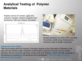
MATERIALS TESTING. Why are metals tested ?. Ensure quality Test properties Prevent failure in use Make informed choices in using materials Factor of Safety is the ratio comparing the actual stress on a material and the safe useable stress. Two forms of testing.

E N D
Why are metals tested ? • Ensure quality • Test properties • Prevent failure in use • Make informed choices in using materials Factor of Safety is the ratio comparing the actual stress on a material and the safe useable stress.
Two forms of testing • Mechanical tests – the material may be physically tested to destruction. Will normally specify a value for properties such as strength, hardness, toughness, etc. • Non-destructive tests (NDT) – samples or finished articles are tested before being used.
HARDNESS TESTING Hardness is the ability to withstand indentation or scratches
Hardness testing machine • The indenter is pressed into the metal • Softer materials leave a deeper indentation
Brinell hardness test • Uses ball shaped indentor. • Cannot be used for thin materials. • Ball may deform on very hard materials • Surface area of indentation is measured.
Vickers hardness test • Uses square shaped pyramid indentor. • Accurate results. • Measures length of diagonal on indentation. • Usually used on very hard materials
Rockwell hardness tests • Gives direct reading. • Rockwell B (ball) used for soft materials. • Rockwell C (cone) uses diamond cone for hard materials. • Flexible, quick and easy to use.
Impact Tests • Toughness of metals is the ability to withstand impact.
Izod test • Strikes at 167 Joules. • Test specimen is held vertically. • Notch faces striker.
Charpy impact test • Strikes form higher position with 300 Joules. • Test specimen is held horizontally. • Notch faces away from striker.
Tensile Testing • Uses an extensometer to apply measured force to an test specimen. The amount of extension can be measured and graphed. • Variables such as strain, stress, elasticity, tensile strength, ductility and shear strength can be gauged. • Test specimens can be round or flat.
Test results Cup and cone fracture signifies a ductile material A shear fracture would indicate a brittle material
Producing graphs Two basic graphs: • Load / extension graph. • Stress / strain graph.
Youngs Modulus (E) E = Stress Strain • Stress = Load Cross section area • Strain = Extension Original length
Youngs Modulus for stress – strain graph • Select point on elastic part of graph • Calculate Youngs Modulus with this point E = Stress Strain
Proof Stress • The stress that causes a % increase in gauge length. • It can be found by drawing a line parallel to the straight part of the graph. • A value can be taken from the vertical axis.
Tensile Strength Tensile strength = Maximum Load Cross section area Maximum load is the highest point on the graph. Often called Ultimate Tensile Strength (UTS)
Creep When a weight is hung from a piece of lead and left for a number of days the lead will stretch. This is said to be creep. Problems with creep increase when the materials are subject to high temperature or the materials themselves have low melting points such as lead. Creep can cause materials to fail at a stress well below there tensile strength.
Fatigue • Fatigue is due to the repeated loading and unloading. • When a material is subjected to a force acting in different directions at different times it can cause cracking. In time this causes the material to fail at a load that is much less than its tensile strength, this is fatigue failure. Vibration for example is a serious cause of fatigue failure. • Fatigue can be prevented with good design practice. • A smooth surface finish reduces the chance of surface cracking. • Sharp corners should be avoided. • Corrosion should be avoided as this can cause fatigue cracks.
Why use NDT? • Components are not destroyed • Can test for internal flaws • Useful for valuable components • Can test components that are in use
Penetrant testing • Used for surface flaws. • The oil and chalk test is a traditional version of this type of testing. Coloured dyes are now used.
Magnetic particle testing • Used for ferrous metals. • Detects flaws close to the surface of the material. • The component to be tested must first be magnetized. • Magnetic particles which can be dry or in solution are sprinkled onto the test piece. • The particles stick to the magnetic field and flaws can be inspected visually by examining the pattern to see if it has been distorted. • The component must be demagnetized after testing.
Eddy current testing • Used for non-ferrous metals • A.C. current is passed through the coil. • The test piece is passed under the coil causing secondary currents called eddy currents to flow through the test piece. This causes a magnetic field to flow in the test piece. • The flaws are detected on an oscilloscope by measuring a change in the magnetic field.
Ultrasonic testing Ultrasonic Sound waves are bounced off the component and back to a receiver. If there is a change in the time taken for the wave to return this will show a flaw. This is similar to the operation of a sonar on a ship. Operation. • The ultrasonic probe sends the sound wave through the piece. • The sound wave bounces off the piece and returns. • The results are then placed on the display screen in the form of peaks. • Where the peaks fluctuate this will show a fault in the piece. Uses. • This is generally used to find internal flaws in large forgings, castings and in weld inspections.
Radiography (X-ray) Testing • The x-ray are released by heating the cathode. • They are then accelerated by the D.C. current and directed onto the piece by the tungsten anode. • The x-rays then pass through the test piece onto an x-ray film which displays the results. • The x-rays cannot pass through the faults as easily making them visible on the x-ray film. Uses. • This is a test generally used to find internal flaws in materials. It is used to check the quality of welds, for example, to find voids or cracks.