Download

1 / 46
460 likes | 477 Views
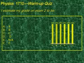
Check the Physics 2135 website for your exam 2 scores. Preliminary average is 66%, with scores ranging from 31 to 200. Remember to submit regrade requests by Thursday after Spring break.

E N D
Announcements • grade spreadsheets with exam 2 scores will be posted today on the Physics 2135 web site • you need your PIN to find your grade • preliminary exam average is about 66% • scores ranged from 31 to 200I will fill in the ??’s during the “live” lecture and in its “.ppt” file. • exam 2 will be returned in recitation Thursday • check that points were added correctly • regrade requests are due by Thursday after spring break On a separate sheet of paper, explain the reason for your request. This should be based on the work shown on paper, not what was in your head. Attach to the exam and hand it to your recitation instructor by next Thursday.
Today’s agenda: Induced current and emf. You must understand how changing magnetic flux can induce an emf, and be able to determine the direction of the induced emf. Faraday’s Law. You must be able to use Faraday’s Law to calculate the emf induced in a circuit. Lenz’s Law. You must be able to use Lenz’s Law to determine the direction induced current, and therefore induced emf. Generators. You must understand how generators work, and use Faraday’s Law to calculate numerical values of parameters associated with generators. Back emf. You must be able to use Lenz’s law to explain back emf.
Magnetic Induction • in lectures 16 and 17, we found that electric current can give rise to a magnetic field Question: Can magnetic field give rise to an electric current? Observation: electric current is induced if magnetic flux through closed circuit (e.g., loop of wire) changes I B • constant magnetic flux does not induce a current
N S v move magnet toward coil “Change” may or may not require observable (macroscopic) motion • a magnet may move through a loop of wire • a loop of wire may be moved through a magnetic field B I I region of magnetic field this part of the loop is closest to your eyes change area of loop inside magnetic field N S rotate coil in magnetic field
changing I induced I changing B • changing current in wire loop gives rise to changing magnetic field which can induce a current in another nearby loop of wire In the this case, nothing observable (to your eye) is moving, although, of course microscopically, electrons are in motion. Induced current is produced by a changing magnetic flux.
Today’s agenda: Induced current and emf. You must understand how changing magnetic flux can induce an emf, and be able to determine the direction of the induced emf. Faraday’s Law. You must be able to use Faraday’s Law to calculate the emf induced in a circuit. Lenz’s Law. You must be able to use Lenz’s Law to determine the direction induced current, and therefore induced emf. Generators. You must understand how generators work, and use Faraday’s Law to calculate numerical values of parameters associated with generators. Back emf. You must be able to use Lenz’s law to explain back emf.
Quantify the induced emf (voltage) Faraday’s Law of Magnetic Induction is magnetic flux through N closed loops of wire Two ways to find sign of the induced emf: • directly from Faraday’s law by using right hand rule and keeping track of sign of B (explained in your text, page 959 of the 14th edition) • more easily from Lentz’s law (see below)
N S I v + - Example: move a magnet towards a wire coil of area A=0.002 m2 with 5 turns. The field changes at a rate of dB/dt =0.4 T/s. Find the magnitude of the induced emf.
Today’s agenda: Induced emf. You must understand how changing magnetic flux can induce an emf, and be able to determine the direction of the induced emf. Faraday’s Law. You must be able to use Faraday’s Law to calculate the emf induced in a circuit. Lenz’s Law. You must be able to use Lenz’s Law to determine the direction induced current, and therefore induced emf. Generators. You must understand how generators work, and use Faraday’s Law to calculate numerical values of parameters associated with generators. Back emf. You must be able to use Lenz’s law to explain back emf.
N S Lenz’s law—An induced emf gives rise to a current whose magnetic field opposes the change in flux. induced magnetic field I v + - More general formulation of Lenz’s law: Any induction effect opposes its cause! If Lenz’s law were not true, then an increase in magnetic field would produce a current, which would further increase the magnetic field, further increasing the current, making the magnetic field still bigger… violates energy conservation
Practice with Lenz’s Law. In which direction is the current induced in the coil? (counterclockwise) (no current) Important: cause of induction effect is change in flux!
(counterclockwise) (clockwise) Important: cause of induction effect is change in flux!
Rotating the coil about the vertical diameter by pulling the left side toward the reader and pushing the right side away from the reader in a magnetic field that points from right to left in the plane of the page. (counterclockwise)
Today’s agenda: Induced emf. You must understand how changing magnetic flux can induce an emf, and be able to determine the direction of the induced emf. Faraday’s Law. You must be able to use Faraday’s Law to calculate the emf induced in a circuit. Lenz’s Law. You must be able to use Lenz’s Law to determine the direction induced current, and therefore induced emf. Generators. You must understand how generators work, and use Faraday’s Law to calculate numerical values of parameters associated with generators. Back emf. You must be able to use Lenz’s law to explain back emf.
Generators • a generator is a device that produces electricity (specifically, an emf) from motion • your text introduces four ways of producing induced emf: 1. Flux change if a wire loop rotates in a magnetic field B A Rotating loop generator side view
2. Flux change if a wire loop expands or contracts in a magnetic field v B B slide-wire generator ℓ dA x=vdt
3. Conductor moving in a magnetic field: motional emf v B B – motion produces voltage difference between wire ends ℓ + This is called “motional” emf, because the emf results from the motion of the conductor in the magnetic field. The other three examples in this lecture are “induced” emf because they involve the change of magnetic flux through a current loop, as described by Faraday’s Law.
4. Flux change if a wire loop moves into or out of a magnetic field
Let’s look in detail at each of these four ways of using flux change or motion to produce an emf.
B A side view S N Rotating loop generators Take a loop of wire in a magnetic field and rotate it with an angular speed . Choose 0=0. Then
B A side view If there are N loops in the coil || is maximum when = t = 90° or 270°; i.e., when B is zero. The rate at which the magnetic flux is changing is then maximum. is zero when the magnetic flux is maximum.
Example: the armature of a 60 Hz ac generator rotates in a 0.15 T magnetic field. If the area of the coil is 2x10⁻² m2, how many loops must the coil contain if the peak output is to be max = 170 V? Not a starting equation. Needs to be derived.
Let’s look in detail at each of these four ways of using flux change or motion to produce an emf. Method 2…
B B Another Kind of Generator: A Slidewire Generator • a U-shaped fixed conductor and a moveable conducting rod are placed in a magnetic field • rod moves to the right with constant speed v v • during time dt, rod moves distance vdt ℓ dA • area of loop increases by dA = ℓvdt vdt x
loop is perpendicular to the magnetic field, thus B = = BA v B B ℓ dA vdt Faraday’s law: x
B Direction of current? • magnetic flux inside the loop increases (area increases) • induced emf causes current to flow in the loop. v Lenz’s law: • system opposes flux increase, so induced magnetic field must be into the page ℓ • induced current is clockwise I dA vdt x What would happen if the bar were moved to the left?
Power and current • if loop has resistance R, current is • electric power dissipated in loop: v B FM FP ℓ Where does the energy come from? • magnetic force on bar I • pulling force necessary to keep bar moving x • power of the pulling force Mechanical energy is converted into electrical energy, electrical energy is dissipated by the resistance of the wire.
Let’s look in detail at each of these four ways of using flux change or motion to produce an emf. Method 3…
Example 3 of motional emf: moving conductor in B field. Motional emf is emf induced in a conductor moving in a magnetic field. “up” v B B • conductor (purple bar) moves with speed v in a magnetic field • electrons in bar experience force – ℓ + Charge separation: • force on the electrons is “up,” • “top” end of the bar acquires a net – charge • “bottom” end of the bar acquires a net + charge.
separated charges produce an electric field E pointing “up” • voltage difference between ends: • electric field exerts “downward” force on the electrons: “up” v B B – ℓ E Equilibrium: magnetic and electric forces are equal and opposite: +
Let’s look in detail at each of these four ways of using flux change or motion to produce an emf. Method 4…
Example 4 of induced emf: flux change through conducting loop. (Entire loop is moving.) I’ll include some numbers with this example. Remember, it’s the flux change that induces the emf. Flux has no direction associated with it. However, the presence of flux is due to the presence of a magnetic field, which does have a direction, and allows us to use Lenz’s law to determine the “direction” of current and emf.
A square coil of side 5 cm contains 100 turns and is positioned perpendicular to a uniform 0.6 T magnetic field. It is quickly and uniformly pulled from the field (moving to B) to a region where the field drops abruptly to zero. It takes 0.10 s to remove the coil, whose resistance is 100 . B = 0.6 T 5 cm
Initial: Bi = = BA . (a) Find the change in flux through the coil. Final: Bf = 0 . B = Bf - Bi = 0 - BA = -(0.6 T)(0.05 m)2 = -1.5x10⁻³ Wb.
(b) Find the current and emf induced. Current will begin to flow when the coil starts to exit the magnetic field. Because of the resistance of the coil, the current will eventually stop flowing after the coil has left the magnetic field. final initial The current must flow clockwise to induce an “inward” magnetic field (which replaces the “removed” magnetic field).
v The induced emf is dA x x
“uniformly” pulled The induced current is
(c) How much energy is dissipated in the coil? Current flows during the time flux changes. E = P t = I2R t = (1.5x10⁻² A)2 (100 ) (0.1 s) = 2.25x10⁻³ J (d) Discuss the forces involved in this example. The loop has to be “pulled” out of the magnetic field, so there is a pulling force, which does work. The “pulling” force is opposed by a magnetic force on the current flowing in the wire. If the loop is pulled “uniformly” out of the magnetic field (no acceleration) the pulling and magnetic forces are equal in magnitude and opposite in direction.
The flux change occurs only when the coil is in the process of leaving the region of magnetic field. No flux change. No emf. No current. No work (why?).
Fapplied D Flux changes. emf induced. Current flows. Work (equal to FD) is done.
No flux change. No emf. No current. (No work.)
I (e) Calculate the force necessary to pull the coil from the field. Remember, a force is needed only when the coil is partly in the field region.
Multiply by N because there are N loops in the coil. where L is a vector in the direction of I having a magnitude equal to the length of the wire inside the field region. F3 L2 L3 I L4=0 Sorry about the “busy” slide! The forces should be shown acting at the centers of the coil sides in the field. Fpull F2 L1 F1 There must be a pulling force to the right to overcome the net magnetic force to the left.
Magnitudes only (direction shown in diagram): F3 L2 L3 I Fpull F2 L1 F1 This calculation assumes the coil is pulled out “uniformly;” i.e., no acceleration, so Fpull = Fmag.
Work done by pulling force: x I Fpull D The work done by the pulling force is equal to the electrical energy provided to (and dissipated in) the coil.