Download
1 / 19
190 likes | 262 Views
Explore the architecture, specifications, and implementation of a cable modem network using Simulink, covering topics like cable data network overview, downstream/upstream specifications, and implementation results.

E N D
Simulink Implementation of a Cable Modem Gina Colangelo Nathan Egan EE194-SDR 05/02/2006
Topics Covered • Cable Data Network Overview • Cable Modem Architecture • Downstream/Upstream Specifications • Simulink Implementation • Implementation Results
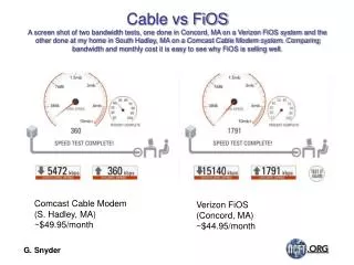
Cable Modem Network Overview • Headend: DOCSIS-certified CMTS (Cable Modem Termination System) • One Headend supports ~ 2000 Cable Modem Users on a single TV Channel • CMTS interfaces the CATV network to the Internet • CMTS output channel combined with TV video signals • CATV Network to Subscriber via coaxial cable • One-to-Two splitter: One signal to Set Top Box (STB), other to Cable Modem • Cable Modem • One Modem can support up to 16 users in a local-area network • PC/Ethernet Card • Cable Modem connected to PC via Ethernet, USB, PCI Bus, etc
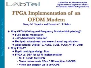
Cable Modem Architecture • Transmit/Upstream • QPSK/QAM Modulator performs: • QPSK/QAM-16 modulation • Reed-Solomon Encoding • D/A Conversion • Up-conversion to the selected frequency/channel • Receive/Downstream • RF Tuner • Converts TV Channel to a fixed lower frequency (6-40MHz) • QAM Demodulator performs: • A/D conversion • QAM-64/256 demodulation • MPEG frame synchronization • Error Correction (Reed-Solomon) • MAC - Media Access Control • Implemented partially in hardware and software • Data and Control Logic
TUNER Diplex Filter (Internal or External to Modem) Analog IF Analog RF Decimate to Symbol Rate QAM Demodulation Dig BB ADC Tunable BPF LNA LPF VGA Fixed Freq Variable Freq Digital Ctrl Logic/Signals Digital Ctrl Logic/Signals Receive Path • Diplex Filter – splits/combines bands for 2-way capability on CATV systems • Tuner – isolates TV channel and mixes it down to Analog IF (6-40MHz) • Analog to Digital Conversion • Decimation Filters to down-sample to the symbol rate (e.g. CIC) • QAM Demodulator • MPEG Frame synchronization • Automatic Gain Control (AGC) • Equalizer – removes distortions, and cancels echoes or multi-path conditions • Carrier Removal • Automatic Frequency Control (AFC) QAM Demodulator Generic Receive Path of a Cable Modem
Downstream Specifications • Frequency Range: 65-850MHz • Bandwidth: 6MHz (USA) or 8MHz (EU) • Modulation: 64-QAM (6 bits/symbol) or 256-QAM (8 bits/symbol) • Data rate: 27-56 Mbps (depends on modulation and bandwidth) • Continuous stream of data • Framing: MPEG-2 (based on DOCSIS spec) • Encryption: DES (Data Encryption Standard) • Reed-Solomon Forward Error Correction * Symbol rate listed under Modulation does not compensate for error correction and other overhead ** Data rates listed in the table use a symbol rate of 6.9 Msym/s for 8MHz BW and 5.2Msym/s for 6MHz BW
Transmit Path • QAM (Burst) Modulator • Reed-Solomon Encoder (Forward Error Correction) • Randomizer/Scrambler – whitens the data • Helps to avoid discrete spurs in output spectrum • Improves synchronization at the receiver since data is more equiprobable • Preamble Insertion • Inserts a training sequence into the system • Transmitted without R-S Encoding or Scrambling • Modulation Encoder (QPSK/16-QAM) • Pulse Shaping (e.g. Raised Root Cosine) • Programmable Interpolation Filters (e.g. CIC) • Programmable NCO, digitally modulates carrier anywhere in the Nyquist Bandwidth • Digital to Analog Conversion • Variable Gain CATV Line Driver QAM Modulator To Diplexer Preamble Insertion Programmable Interpolation Filter Program- mable NCO Digital Data In Pulse-Shaping FIR Filter Modulation Encoder (QPSK/16-QAM)) Reed- Solomon Encoder DAC MUX Randomizer Programmable Interpolation Filter Pulse-Shaping FIR Filter Variable Gain CATV Line Driver Fixed Freq Digital Control Logic/Signals
Upstream Specifications • Frequency Range: 5-65 MHz • Variable Bandwidth: 200 kHz to 3.2 MHz (2 MHz typically) • Modulation: QPSK (2 bits/symbol) or 16-QAM (4 bits/symbol) • Data rate: Variable 320 Kbps to 10 Mbps • Transmit bursts of data in timeslots (TDM) • Encryption: DES • Reed Solomon Forward Error Correction
I Xmit FIR 32x I Input Bit Stream Raised Root Cosine Xmit Filter QAM Modulator GAIN RF OutputSignal Q Xmit FIR 32x Q SIN COS NCO TX Implementation • 16-QAM Modulation – 320ksps • Raised Root Cosine Filter: • Upsamples by 8, data rate at output = 2.56Msps • Roll-off factor = 0.7 • FIR Interpolation Filter • Polyphase Implementation • Interpolates by 32, data rate at output = 81.92Msps • Order FIR filter = 60, Cutoff Frequency = 320kHz • NCO - Mixes signal up to 30MHz • Gain factor of 30 to compensate for losses throughout path
TX Spectrum Output from the RRC Filter: Power MHz -1.28 1.28 0 Sampled signal after interpolation* Power FIR Interpolation Filter Response MHz 0 -40.96 40.96 Output signal from up-conversion Power MHz -40.96 40.96 30 -30 0 *Interpolation Images will occur every 2.56MHz
RX Implementation I Rx FIR 32x I • NCO - Mixes signal down to Baseband • FIR Decimation Filter • Polyphase Implementation • Decimates by 32, data rate at output = 2.56Msps • Order FIR filter = 10, Cutoff Frequency = 1.28MHz • Raised Root Cosine Filter: • Downsamples by 8, data rate at output = 320ksps • Roll-off factor = 1 • 16-QAM Demodulation Raised Root Cosine Rx Filter RF Input QAM Demodulator Baseband Signal Q Rx FIR 32x Q COS SIN NCO
RX Spectrum Power Input signal to demodulator MHz -40.96 40.96 30 -30 0 Signal after the down-conversion Power Input Signal -60 MHz 60 0 Sampled signal after decimation Power FIR Decimation Filter Response MHz 0 -1.28 1.28 Input to the QAM demodulator Power RRC Filter Response MHz -0.32 0 0.32
Simulink Results – TX Path TX Signal After Pulse Shaping TX Signal After 32X Interpolation TX Signal after Up-Conversion
Simulink Results – RX Path Rx Signal After 32X Decimation Rx Signal After Down-Conversion
System Results – Time Domain Delay Through Data Path
System Results 2 RX Constellation TX Constellation
Simulink Results - BER • BER with current implementation = 0.9741 • What effected BER? • Design of the FIR • SNR of datapath (AWGN Channel) • Design of Raised Root Cosine Filter • Main Tradeoff • Dynamic Range/Spurious Content vs EVM/BER • Better Implementation • Compensation Filter after Interpolator and Decimator
Websites for More Info: • http://www.ciscopress.com/articles/article.asp?p=31289&seqNum=2&rl=1 • http://www.iec.org/online/tutorials/acrobat/cable_mod.pdf • http://www.cable-modems.org/tutorial/index.htm#TOC • http://www.broadcom.com/collateral/pb/3349-PB01-R.pdf • http://www.analog.com/UploadedFiles/Data_Sheets/13374136AD9853_c.pdf • http://www.wideband.com/products/Modems/QAM20Mod/QAMmod.html • http://focus.ti.com/lit/an/slwa023/slwa023.pdf • http://www.broadcom.com/collateral/pb/3419-PB02-R.pdf • http://www.cableaml.com/website3/wireless_catv/descriptions.htm • http://www.fcc.gov/mb/engineering/cablemqa.html • http://www.cablemodem.com/ • http://www.nextgendc.com/index.htm • http://computer.howstuffworks.com/cable-modem.htm • http://compnetworking.about.com/od/dslvscablemodem/a/dslcablecompare.htm