Download
1 / 15
170 likes | 487 Views
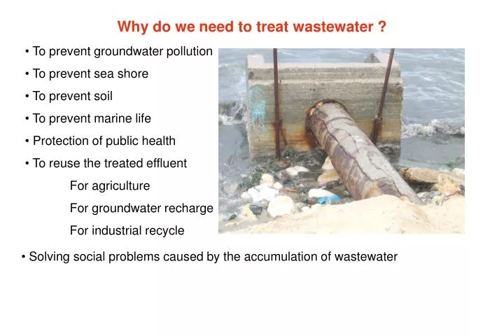
Why do we need to treat wastewater ?. To prevent groundwater pollution To prevent sea shore To prevent soil To prevent marine life Protection of public health To reuse the treated effluent For agriculture For groundwater recharge For industrial recycle.

E N D
Why do we need to treat wastewater ? • To prevent groundwater pollution • To prevent sea shore • To prevent soil • To prevent marine life • Protection of public health • To reuse the treated effluent • For agriculture • For groundwater recharge • For industrial recycle • Solving social problems caused by the accumulation of wastewater
Technical goals of Wastewater treatment • Separation of solids from liquid • Stabilization of separated solids • disinfection of pathogenic micro-organisms • Proper reuse or disposal of treated liquid and solids Wastewater treatment methods Physical Chemical Biological Aerobic Anaerobic Precipitation Adsorption Disinfection Screening Mixing Flocculation Flotation Filtration Sedimentation Gas Transfer
Wastewater Treatment Process O2 • Secondary treatment • Aerobic, anaerobic lagoons • Trickling filter- activated sludge-oxidation ditch • Mostly BOD removal technology • Primary treatment • screening • grit removal • removal of oil • sedimentation • Tertiary treatment • Nitrate removal • Phosphorus removal • Disinfection
Bar screens Screens are used in wastewater treatment for the removal of coarse solids. Screens are either manually or mechanical cleaned. • Characteristics of manual bar screen • Bar spacing is in range of 2-5 cm • The screen is mounted at an angle of 30-45 • Bars are usually 1 cm thick, 2.5 wide • Minimum approach velocity in the bar screen channel is 0.45 m/s to prevent grit deposition. • Maximum velocity between the bars is 0.9m/s to prevent washout of solids through the bars. • Characteristics of mechanical bar screen • Bar spacing is in range of 1.5-4 cm • The screen is mounted at an angle of 30-75 • Bars are usually 1 cm thick, 2.5 wide • Minimum approach velocity in the bar screen channel is 0.45 m/s to prevent grit deposition. • Maximum velocity between the bars is 0.9 m/s to prevent washout of solids through the bars.
Design of the bar screen channel (Approach Channel) The cross section of the bar screen channel is determined from the continuity equation: Qd = AcVa Ac = Qd/ Va The head loss through the bar screen Qd = design flow, m3/s Ac = bar screen cross section, m2 Va = Velocity in the approach channel, m/s Hl = head loss Va = approach velocity, m/s Vb = Velocity through the openings, m/s g = acceleration due to gravity, m/s2 Usually, rectangular channels are used, and the ratio between depth and width is taken as 1.5 to give the most efficient section.
Example 1 A manual bar screen is to be used in an approach channel with a maximum velocity of 0.64 m/s, and a design flow of 300 L/s. the bars are 10 mm thick and openings are 3 cm wide. Determine The cross section of the channel, and the dimension needed The velocity between bars The head loss in meters The number of bars in the screen 1. Ac= Qd/Va= 0.3/0.64 = 0.47 m2 Ac= W x1.5W =1.5 W x W 3. Head loss: W = 0.56 m, Depth (d) = 1.5 W = 0.84 m = 0.024 m 2. 4) n tbar + (n-1)Sc = W n x 1 + (n-1) x 3= 56 n= 14.75 = 15 = 0.84 x 0.56 (3/3+1) = 0.35 m2 From continuity equation: Va Ac= Vb Anet Vb= 0.64 x 0.56 x 0.84/0.35 = 0.86 m/s < 0.9 m/s ok
Settling Theory Vs = settling velocity of particles = density of particles = liquid density d = particle diameter CD = drag coefficient Vh= scour velocity = Friction factor of particles = Darcy-weisbach friction factor Vh Vs
Example 2 A suspension contains particles of grit with a diameter of 0.2 mm and specific gravity of 2.65. For particles of this size CD= 10, f= 0.03, and = 0.06. The suspension also contains organic solids of same size for which the specific gravity is 1.10 and and f are unchanged. Determine the settling velocity of the grit and the scour velocity of grit and organic material. Solution Settling velocity of particles = 2.1 cm/s Scour velocity of particles = 23 cm/s Scour velocity of organic solids = 5.6 cm/s
Grit Chamber Goals: Removal of inorganic matter which has high density > 2000 kg/m3 and particle size 0.1 to 0.2 mm in order to protect pumps from abrasion and to protect digesters from getting clogged. Vh A = W * H = Q/Vh Vs / Vh = H / L H A VS W L Example 3 Design a grit chamber for Treatment plant having a daily flow of 11000 m3. Use the values of Vh and Vs from example 3. Solution A= W*H= 0.13 (m3/s)/0.23 (m/s)= 0.55 m2 Assume W= 1 m , then H = 0.55 m Vs/ Vh= H/L 2.1/23 = o.55/L L= 6.04 m
Grit chamber control device design • The horizontal velocity is very important to the proper function of the grit chamber • The velocity can be held constant regardless of the flow, by proper combination of basin cross section and the control device. • For a constant velocity, the basin cross section must be proportioned so that: • Vh = Constant • The condition of constant velocity is maintained, provided the width of the basin varies so that Yn-1 = KX .where n is the discharge coefficient of the control section. • If the control section is rectangular in cross section (like a Parshall flume) n will be approximately 1.5, thusY =CX2and the channel cross section must be parabolic. • With a proportional flow weir , n= 1 and X=C. The channel cross section in this case is rectangular , which somewhat simplified construction. • The actual proportions of the channel and weir must be selected together to provide the necessary conditions for grit removal.
Example 4 Design a grit –removal system consisting of three identical channels for a plant which has a peak flow of 80,000 m3/day, max flow of 65,000, an average flow of 50,000 m3/day and a minimum flow of 20,000 m3/day. Use parabolic channels. The design velocity (Vh) is 0.25 m/s. Solution Design a grit –removal system consisting of three identical channels for a treatment plant which has a peak flow of 80,000 m3/day, an average flow of 50,000 m3/day and a minimum flow of 20,000 m3/day. Use parabolic channels. The design velocity is 0.25 m/s.
1500 1110 1000 810 450 mm Channel and control device cross section
Example 5 Design a set of rectangular grit basins with proportional flow weir for a plant which has a peak flow of 80,000 m3/day, max flow of 65,000, an average flow of 50,000 m3/day and a minimum flow of 20,000 m3/day. Use three basins. Make the peak depth equal to the width. The design velocity (Vh) is 0.25 m/s. Solution
Proportional flow weir for use with rectangular grit chamber Rejected area Area equals to rejected area 7.5 cm