Download
1 / 29
380 likes | 608 Views
Overview of the KSTAR commissioning. M. Kwon 3 June, 2008. Commissioning Objective. 1. To test the components and systems after system integration. 2. To demonstrate that systems are in accordance with the design values and the performance criteria.

E N D
Overview of the KSTAR commissioning M. Kwon 3 June, 2008
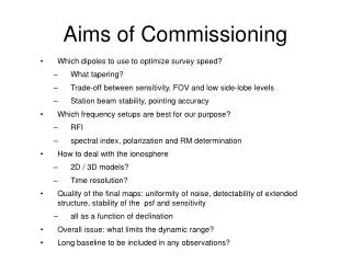
Commissioning Objective • 1. To test the components and systems after system integration. • 2. To demonstrate that systems are in accordance with the design values and the performance criteria. • 3. To identify any defect preventing the device operation and plasma experiments.
Checkpoints during the Commissioning 1. Vacuum quality in every environment, before & after cool-down. 2. Controlled cryogenic cool-down of all superconducting magnet system. 3. Status of the SC magnet assembly without individual cool-down test. 4. Performance of the Nb3Sn magnet system during the 1st plasma discharge.
Commissioning Milestones Cooled-down May 02 1st Plasma June 30
Vacuum commissioning • Major Operation • Vacuum pumping system operation • VV baking operation • Discharge cleaning • Gas fuelling system operation • Operation Results • Base pressure of VV • Target : 5 x 10⁻⁷ mbar, achieved < 3 x 10⁻⁸ mbar • Base pressure of cryostat at room temperature • Target : 1 x 10⁻⁴ mbar, achieved < 1 x 10⁻⁵ mbar • VV baking : 100 0C • DC glow discharge cleaning(H2, He) • Fueling system operation & testing • Gas : He • No. of Electrodes : 1 • RF Power: 200 W • DC Bias Voltage: 400 V • DC Current: 4 A • Operation Pressure: • 6.0 10-3 mbar
Cool-down commissioning • Major Operation • Operation & control of the helium refrigeration system & helium distribution system (9 kW @ 4.5 K). • Controlled cool-down of cold systems: SC magnet, structures, busline, thermal shields, current leads. • Superconducting phase transition • Control & Monitoring • Hydraulic parameters • Temperature, pressure & flow distribution • Mechanical monitoring • Stress & displacement • Superconductor monitoring • Coil resistance & SC phase transition • Safety • Vacuum & helium pressure monitoring
KSTAR SC coils CS4U CS3U CS2U CS1U CS1L CS2L CS3L CS4L
Cool-down of KSTAR In April 26, KSTAR superconducting coils were successfully cooled-down.
Controlled cool-down (∆T < 50 K) The maximum temperature difference in the magnet structures was carefully controlled within 50 K during the cool-down.
Mass flow rate • The gaseous helium of maximum 200 g/s was supplied by the clod box. • After cool-down, the SC coils were cooled by the 600 g/s supercritical helium of cryogenic circulator to its operating temperature.
Temperature distribution in the thermal shields • The cryostat thermal shields were well cooled below 70 K. • The maximum temperature of the CRTS measured in 180 K on the blank cover plate without cooling lines. • The temperature of the vacuum vessel shield was distributed in 90 K ~ 120 K
Cryostat vacuum during cool-down • After cool-down, the vacuum pressure of the cryostat reached to 2.6E-8 mbar. • The partial pressure of each gas greatly decreased as coil cooling and the residual helium gas was kept almost constant pressure level.
SC transition measurement SC transition measurement • The superconducting phase transition of the SC coils was clearly observed during the 1st cool-down. • The SC transition of Nb3Sn and NbTi coils appeared at 18K and 9K, respectively. [The results of the measured Tc of SC coils] The measured Tc of the 16 TF coils
Joint Resistance • The voltage drops were measured at each SC bus-line, which consists of several numbers of electrical joints. • The joint resistances were estimated by linear fitting to the measured V-I curves. • All of the KSTAR lap joint resistances satisfied the design value of 5 nΩ. [The KSTAR lap joint of the SC bus-line]
Radial displacements of the toroidal ring • Radial displacements of the toroidal ring from 293 K to 11 K were measured in the range of 7.66 mm ~ 7.93 mm, which is comparable of the FEM analysis result. • The maximum deviation of the segments is just 0.006 % as compared with the diameter of the ring, 5780 mm. Reference ; “KSTAR Magnet Structure Stress Analysis”, Efremove, July, 2003
SC Magnet Commissioning • Major Operation • Superconducting joint resistance measurement • Insulation test at cryogenic temperature • Magnet power supply control • TF coil charge & discharge : up to 15 kA (B0 = 1.5 T, Bm = 3.1 T) • PF coil charge & blip operation • Control & Monitoring • Coil current & voltage • Field on SC magnet, in vacuum vessel • Coil performance under the dc & pulse field variation • Interlock & safe discharge (quench discharge)
TF magnet SD & FD test QD & MD adjust SD & FD test at 5 kA
PF Blip Operation PF1 : 2.7 kA PF4 : 2.6 kA PF2 : 2.1 kA PF5 : 2.1 kA PF6 : 2.3 kA PF3 : 2.8 kA PF7 : -2.3 kA
Status of KSTAR ECH commissioning 84 GHz, 500kW CPI Gyrotron (2008. 4. 21) • Gyrotron installation: 2008. 4. 21 • GyrotronAging: 2008. 4. 28 – • 400 kW, 100 ms RF aging • Transmission line is under aging Beam current Body current (blue) Forward RF signal Body voltage (green) Forward RF signal (at the end of transmission line) Beam current (pink) Cathode voltage (yellow) Backward RF signal Gyrotron operation parameters (80 kV, 18 A, 100 ms) RF power: ~ 400 kW, 100 ms pulse
Plasma Start-up Commissioning • Major Test • Fueling & wall conditioning • Heating system readiness test • MPS and BRIS tuning • ECH pre-ionization • Plasma start-up and optimization • Control & Monitoring • Coil performance under the dc & pulse field variation • Measurementof plasma parameters (current, density, • image, loop voltage, H-alpha etc.) • Change of ECH parameters • Plasma control and monitoring
ECH Power (A.U) PF Current (A) Line Density (1019 m-2) H-α Intensity (A.U) Loop Voltage (V) Total Current (A) Time (sec) KSTAR SHOT number 586 (2008. 05. 30)
Long-term operation plan • KSTAR will be one of the most effective devices for ITER relevant operation and physics for reliable fusion reactor. • Accumulation of the technical know-how for the superconducting tokamak operation • Leading the high performance steady-state plasma experiment PHASE 1 PHASE 2 PHASE 3 PHASE 4 Phase 07 08 09 10 11 12 13 14 15 16 17 18 19 20 21 22 23 24 25 Year SC Tokamak Operation Technology Steady-state Operation High-beta, AT Operation Steady-state AT Goal • First plasma • SC tokamak operation technology (Bt = 3.5 T) • D-shaped plasma • (Ip >1 MA, D2) • H -mode achievement • Collaboration for operation • Long pulse operation (tpulse> 100 s) • AT operation Tech. • (Pheat< 20 MW) • ITER pilot device operation • Collaboration for steady-state operation • Long pulse operation (tpulse > 300 s) • Stable AT operation (Pheat > 20 MW) • ITER satellite operation • Collaboration for advanced research • High beta AT mode & long pulse • Reactor material test (divertor, blanket) Activities Milestone 1st Plasma 1MA D-D Reaction 100 s Ion Temp > 10 keV ITER Construction Start ITER 1st Plasma