AC Power Analysis: Understanding Power Triangles and Power Factor Correction
This lecture revisits AC power analysis through concepts like average power, complex power, and power triangles. Understanding RMS values and power factor is crucial. Learn about power factor correction and its impact on power delivery efficiency. Follow examples to calculate complex power and average power in circuits. Discover the significance of power factor correction in maintaining efficiency.

AC Power Analysis: Understanding Power Triangles and Power Factor Correction
E N D
Presentation Transcript
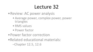
Lecture 32 Review: AC power analysis Average power, complex power, power triangles RMS values Power factor Power factor correction Related educational materials: Chapter 12.5, 12.6
AC power analysis • Average power: • Average power in terms of RMS (or effective) values: • Complex power:
Power triangles • Complex power (rectangular form): • Real (average) and reactive power: • Presented graphically:
Power factor (pf) • Power factor: • Load impedance:
Example 1 For the circuit below, determine: (a) the complex power delivered by the source (b) the average power delivered by the source
Outline problem on previous slide: • 1. find equivalent impedance • 2. find source current • 3. complex power = VI*/2 • 4. Average power = (Vm*Im/2)*cos(thetav-thetai)
Effect of pf on power delivery • If v - i 0, we have some reactive power that is not consumed by the load • The current provided to the load is higher than necessary • Results in additional power dissipated during delivery • Power companies don’t like this!
Power factor correction • Power companies may require that users maintain a minimum power factor • e.g. pf > 0.9 • Most large loads are inductive in nature • e.g. inductive motors • Power factor correction may be necessary • The approach must be inexpensive & simple to implement • Adding a capacitor in parallel with the inductive load will increase the power factor
Power factor correction – continued • We have an inductive load with some power factor cos1: • The power triangle is shown below:
Power factor correction – continued again • We can increase the power factor by adding a capacitor in parallel with the load: • The power triangle then becomes:
Example 2 – power factor correction For the circuit below if (a) Determine the power factor (b) Re-design the circuit so that pf = 1