Download
1 / 19
190 likes | 401 Views
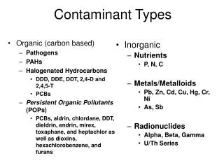
Contaminant Transport and Filtration Issues with DOAS. ASHRAE Louisville Meeting June 23, 2009. Stanley A. Mumma, Ph.D., P.E. Prof. Emeritus, Architectural Engineering Penn State University, Univ. Park, PA sam11@psu.edu. Web: http://doas-radiant.psu.edu. Objective.

E N D
Contaminant Transportand Filtration Issueswith DOAS ASHRAE Louisville MeetingJune 23, 2009 Stanley A. Mumma, Ph.D., P.E. Prof. Emeritus, Architectural Engineering Penn State University, Univ. Park, PA sam11@psu.edu Web: http://doas-radiant.psu.edu
Objective • Dispel the common perception that DOAS is inferior to all air system when contaminant flushing rates from occupied spaces are considered. • Shift the DOAS filter selection paradigm.
DOAS Defined High Induction Diffuser Cool/Dry Supply OA DOAS Unit w/ TER, CC, & Filtration RA Building with Sensible and Latent Cooling Decoupled Parallel Sensible Cooling System
Facility floor area and zoning for case study 1,000 ft2 Exterior Zone 1 9,000 ft2 Exterior Zone 2 10,000 ft2 Interior Zone 3 10 ft high ceilings--all zones
Case Study Conditions • VAV system: • Supply air (SA) flow rate, 16,000 cfm, of which 4,000 cfm is OA. • Perimeter zones 1 and 2, each receives 1 cfm/ft2 of supply air via a shut off box VAV system. Since the SA is 25% OA, then each perimeter zone is receiving 0.25 cfm/ft2. • Interior zone 3 receives 0.6 cfm/ft2 of supply air via a VAV system, i.e. 0.15 cfm/ft2 OA • DOAS: • OA flow for the facility, 4,000 cfm uniformly distributed in each zone, or 0.20 cfm/ft2.
Transient analysis is based upon the following simplifying assumptions: • Well mixed zones. • No interzonal transfer. • Contaminants stay suspended. • VAV system is analyzed while operating in the minimum OA mode (4,000 cfm OA), and a supply airflow rate of 16,000 cfm. Releases during full economizer mode (resulting in very high peak space concentrations when releases occur near the OA inlet) will not be presented. • The capacitance of the duct system, and its associated influence on the transient response, is neglected.
VAV System Schematic Filter, hf 3 2 1
DOAS Schematic Filter, hf 3 2 1
Transient dimensionless concent’n from release near OA inlet w/ hf = 0% VAV Zone 1 & 2 DOAS VAV Zone 3
Transient concent’n from release near OA inlet w/ VAV hf = 80% & DOAS hf = 98% NOTE: Exposurew/ DOAS is 1/425that of VAV. VAV Zone 1 & 2 VAV Zone 3 DOAS
DOAS filter h necessary to match the space concent’n/exposure after 60 min. for a given VAV filter h. Ref: OA intake occurances. = conc. Paradigm shift!! = h = exp
Filter Optimization Assumptions • Same SA flows as in transient analysis: VAV 16,000 cfm; and DOAS 4,000 cfm. • Assume that the filter loading profile is exponential, causing the average pressure drop over the life of the filter to be:[(Dploaded opt - Dpclean opt)/2]*Fill-ratio. 0.87 Fill-ratio used. • Reference replacement frequency is 3 months for VAV and 6 months for DOAS • fan/motor combined efficiency, 60%. • Electrical cost, $0.10/kWh. • Term of analysis, 5 years. • Fan operating hours per year, 4160 hours. • Neglect the time value of money and inflation.
Filters used in the Optimization Merv 13& 14 Filter94 & 98% h Merv 11 Filter75% h Merv 16 Filter99.7% h
Conclusions • A common attitude that contaminant flushing is a problem with DOASs is not warranted when the proper DOAS filter is selected, i.e. one better than the filter used in a comparably performing VAV system. • The old “equivalence” paradigm needs to change. • Guidance is offered, at least for one set of conditions, on DOAS filter efficiencies. And a method is provided for use on other sets of conditions. • Finally, contrary to conventional wisdom, the selection of better and more expensive DOAS filters resulted in optimized performance costing less— far less —than VAV systems.