Download
1 / 23
230 likes | 370 Views
Principles of Flight section 1. This basic series of lectures should give you an understanding of why a glider flies. Now, its pretty obvious that a wing develops some kind of upward force as it passes through the air; the question is--- how?

E N D
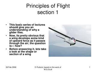
Principles of Flightsection 1 • This basic series of lectures should give you an understanding of why a glider flies. • Now, its pretty obvious that a wing develops some kind of upward force as it passes through the air; the question is--- how? • Before answering it, lets take a look at the shape or section of a wing D Puttock, based on the work of W.G.Scull
The wing section 1 2 3 4 Here we have sections cut through six different wings, and these show the progress that has taken place. We can almost forget about the flat and curved plates although we still use the flat plate for some explanations. Comparing the next four sections, it is apparent that changes have taken place which will be most obvious when comparing the Gottingen(1) with the modern WortmannFX(4). The modern section is slimmer and less cambered. Less obvious is the fact that the thickest part of the section is now further back. Now all this may appear to be rather academic, but later on we will return to this diagram and see that the things we have touched on here will be much more significant. Next we are going to look at the airflow around wing sections. Principles of Flight D Puttock, based on the work of W.G.Scull
Airflow---representation by streamlines Consider the statement that “for all theoretical and experimental work the object is considered stationary with the airflow moving past it”. The reason for this is that if we wish to make measurements of the forces on a wing then it is very much easier if the wing is stationary. The diagram represents airflow diverging around a flat plate which it does symmetrically and there are’nt any forces pushing up or down on the plate. Principles of Flight D Puttock, based on the work of W.G.Scull
Angle of Attack If we change the angle of the plate in relation to the airflow, as shown here, the airflow will be deflected downwards which will push the plate upwards. The angle at which the plate is presented to the airflow is called the angle of attack. Measuring this angle relative to a flat plate is easy; to measure it relative to a wing section is less easy and what is required is some suitable datum. Principles of Flight D Puttock, based on the work of W.G.Scull
Chord Line Here we have the chord line, which is the reference datum of the wing section, drawn in. It passes through the forewardmost point of the leading edge and the back of the trailing edge; the angle of attack is the angle between the chord line and the relative airflow. It should be noted that if we were to measure this angle—something we rarely do in practice—it would be relative to the airflow sufficiently far from the wing to be undisturbed by the wing’s presence. As the airflow exerts a force on the wing, we want to have some way of representing this. Principles of Flight Chord line Angle of Attack D Puttock, based on the work of W.G.Scull
Representation of forces--- a pressure may be shown thus: The diagram shows how the force could be represented if it were a uniform force and if ,say, the area of the plate were 10 square feet and the force on each square foot was 2lbs, then the total force on the plate would be 2*10=20lbs. We could represent this more conveniently by a single force of 20lbs so long as the single forcewas having the same overall effect on the plate as the uniform pressure. Principles of Flight D Puttock, based on the work of W.G.Scull
Total Aerodynamic reaction This is shown here. The total force on the plate is called the total aerodynamic reaction and the point through which it acts is called the centre of pressure. At this point we will summarise what we have done so far. Principles of Flight The centre of pressure D Puttock, based on the work of W.G.Scull
Summary There some abbreviations in this diagram for you to remember. There is also one term missing; can you say what it is? Because I have shown a flat plate rather than a wing section, the chord line is not drawn. One other point which is very important is that the relative airflow is no longer shown as horizontal. The relative airflow can be from any direction; it depends entirely on which way the glider is flying and has nothing to do with the horizontal, the vertical or any other direction. The next slide has the rather imposing title”Resolution of Forces” The principles of Flight TR c.p Relative airflow Angle of Attack D Puttock, based on the work of W.G.Scull
Resolution of forces If we don’t get too put off by this and work through the diagrams in turn it will eventually become apparent why we need to do this. Consider the first statement, 2If there are two forces acting on a body we can represent them if required by a single force”. Consider the upper diagram. Remember that in this way of showing forces, the length of the lines indicates the size of the force. The body has two equal and opposite forces acting on it cancel each other out. A simple analogy is your sitting on that chair---pushing down on it with a certain force and the chair pushing back up with an equal and opposite force. This case is easy to understand, the two lower diagrams are less easy. Principles of Flight R=0 To determine the single equivalent Force construct a parallelogram f1 f1 R R f2 f2 D Puttock, based on the work of W.G.Scull
Resolution of forces Here we have two examples of a body acted upon by two forces; force 1,f1, and force 2,f2,and, as the statement above them says, “ to determine the single equivalent force, we construct a parallelogram. How? Well look at one or other of the lower diagrams again and note the dotted lines called construction lines. This is how we go about it; the diagram starts with only f1 and f2. From the end of f1draw a line parallel to f2 and from the end of f2 draw a line parallel to f1; from the body, represented by the square, to the point where the two construction lines intersect draw a line---the diagonal of the parallelogram—and this is the resultant force. The only difference between the two diagrams is that one is a rectangle and the other is a parallelogram. The principle in each case is the same and the process is reversible. Principles of Flight R=0 To determine the single equivalent Force construct a parallelogram f1 f1 R R f2 f2 D Puttock, based on the work of W.G.Scull
Resolution is a reversible process It’s still done with a parallelogram. Taking force f in the upper diagram, we can divide it into two to produce R1 and R2. The effect on the body of R1 and R2 is the same as that of a single force f, but in this diagram I have chosen the directions of R1 and R2. I might equally well have chosen the directions as the lower diagram indicates; the force f in each diagram is the same in size and direction. The second statement sums that up for you. This process will now be applied to the total aerodynamic reaction. Principles of Flight R1 f R2 We may select direction of replacement forces R1 f R2 D Puttock, based on the work of W.G.Scull
The choice of directions is made for you---at right angles and parallel to the relative airflow which is the direction of motion. This time, the parallelogram is a rectangle and it shouldn’t need any further explanation. Realise that, having resolved the force TR into L and D, lift and drag, we don’t have all three forces ac\ting. L and D are replacements for TR, and the whole process is just a convenient piece of jiggery pokery used by engineers; neverthe less it has its uses. Principles of Flight TR L D D Puttock, based on the work of W.G.Scull
LIFT-that part of TR acting at right angles to the the free airflow. DRAG-that part of TR acting parallel to the free airflow. To summarise: Lift is defined as that part of the total reaction acting at right angles to the free airflow. Drag is defined as that part of the total reaction acting parallel to the free airflow. “The better the ratio of lift divided by the drag, the more efficient is our wing” Principles of Flight D Puttock, based on the work of W.G.Scull
We will now consider why the wing section is more efficient than the flat plate. In the upper diagram, the airflow around a wing is illustrated. The airflow has to diverge to pass around the wing and the path the air takes over the upper surface is different to that over the lower surface. In the case of the flat plate we considered the lifting effect from the under surface only. Now we are going to see that the upper surface of a wing contributes to the lifting force. How it does this is best illustrated by considering the lower diagram which shows a device called a venturi tube. This device offers a gradual and progressive restriction to the passage of air; as it passes through it must accelerate and is at a maximum at the throat or narrowest part.As a result of this increase in speed, there is a drop in pressure, a special type of venturi tube would show this. Principles of Flight The wing section The venturi tube D Puttock, based on the work of W.G.Scull
This venturi has several “U” shaped tubes connected to it. They are filled with fluid and if the pressure is the same on both sides, the levels of fluid would be the same. Blow air through the venturi and we would find that levels in the left hand sides would rise, as illustrated, showing that the pressure reduction is biggest at the narrowest part of the venturi. This effect will still be apparent if we removed the top half of the venturi, but it would be less pronounced. This effect can be illustrated by blowing over a piece of paper; if we stop blowing over the paper, the pressures on either side will be equal and the paper will hang down under its own weight. Principles of Flight The venturi— indications with flow taking place D Puttock, based on the work of W.G.Scull
Bernoulli’s theorem Energy due to pressure (P) + energy due to velocity (V) remains constant: P + V = K It is almost inevitable that there should be some theorem attached to all this. It is not essential that you know it, but just in case it crops up, here it is. More simply it is a swings and roundabouts situation, increase one and you decrease the other. Mathematically this is an over simplification, but if you know the formula in detail, don’t show off or confuse your neighbour by telling it to him. Principles of Flight D Puttock, based on the work of W.G.Scull
Principles of Flight • SUMMARY • With increased velocity there is reduced static pressure. • With decreased velocity there is increased static pressure D Puttock, based on the work of W.G.Scull
Now lets look at how much lift comes from the upper surface of the wing and how much from the lower. The ratio varies with different angles of attack but as a rough guide it is two thirds to one third. This diagram represents the pressure changes over the wing. Realise that it is a reduction of pressure above and an increase below and that the maximum pressure reduction occurs over the thickest part of the wing. Look at the lifting force in numerical terms to get some idea of the pressure changes involved. Lets work through the information below the diagram a line at a time. Wing loading is the weight of the glider divided by its wing area, say 1200 lbs divided by 200 square feet:- 6 lbs per square foot. Lift must support the weight so that each square foot must have a lifting force of 6 lbs. Pressure changes are really quite small 2/3 1/3 Principles of Flight Lift distribution Pressures: Atmospheric 2117 lb/sq ft Above wing 2113 lb/sq ft Below wing 2119 lb/ sq ft D Puttock, based on the work of W.G.Scull
Lift coefficient CL Now lets look at the relationship between the lift a wing generates and the angle of attack.---the “Lift Coefficient” The relationship is presented in graphical form and from it, for any given angle of attack, we can determine the lift coefficient. It is called the lift coefficient because it does not have any units, pounds, kilogrammes or the like. If this raises questions in your mind, don’t worry. The reason for introducing the graph at this stage is you will be using this diagram later on, and you should be able to recognise it. We change our airspeed by changing the angle of attack. “Unaccelerated flight” simply means flight at a steady airspeed. CL 1.0 5° 0 ° 5 ° 10 ° 15 ° 20 ° Principles of Flight For each angle of attack There is only one airspeed (in unaccelerated flight) D Puttock, based on the work of W.G.Scull
Other factors affecting lift Speed squared V² Air density ρ Wing area S Other factors affecting lift are shown here We’ll deal with wing area and air density first. For a given glider the wing area will not vary, nor will air density---represented by the Greek symbol (rho)– unless the height is changing very rapidly indeed. Lets come back to speed: Amplifying an earlier statement, that is” if we change the angle of attack, we change the airspeed” So, at a high speed, although a lot of lift will be generated because of speed alone, not very much will be generated from the angle of attack. The next slide explains. Principles of Flight D Puttock, based on the work of W.G.Scull
The point to realise is that the lifting force is much the same at all moderate airspeeds. However , we change speed by altering the angle of attack and therefore also the lift co-efficient, so there is a large lift coefficient at low speed and a low coefficient at high speed. If the lift is to remain approximately constant, then where the CL contributes a lot the speed contributes little and where CL is small then the speed must be a major contributory factor in generating lift. Principles of Flight Large CL Small CL Low speed High speed D Puttock, based on the work of W.G.Scull
Lift = CL.½ρV².S The relationship between li coefficient and angle of attack should be more apparent if you study this formula. Principles of Flight D Puttock, based on the work of W.G.Scull
TEST Section 1 • Comment on the fundamental changes in wing sections in the development from the early types to the modern laminar flow section. • Draw a diagram showing the relationship between wing section, chord line, relative airflow, total aerodynamic reaction and centre of pressure. • The forces acting on a glider in steady flight are total reaction and weight. Show how the total reaction can be resolved into 2 parts. • Define Lift and Drag. • A large part of the lift derived by awing is attributable to the effect from the upper surface. Give a simple example to illustrate this. D Puttock, based on the work of W.G.Scull