Spatial Analyst Techniques: Merging, Projecting, and Clipping DEMs in ArcGIS
260 likes | 396 Views
This guide covers key tasks in ArcGIS using the Spatial Analyst extension. Learn to enable the Spatial Analyst extension, add the corresponding toolbar, and execute critical operations such as merging Digital Elevation Models (DEMs), projecting DEM data from one coordinate system to another, and clipping DEMs to a specific area. Step-by-step instructions for each task ensure accurate processing, allowing users to effectively manipulate and analyze elevation data for various applications in GIS.

Spatial Analyst Techniques: Merging, Projecting, and Clipping DEMs in ArcGIS
E N D
Presentation Transcript
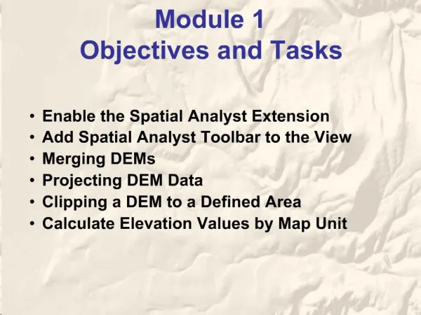
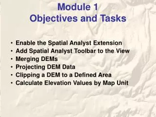
Module 1 Objectives and Tasks • Enable the Spatial Analyst Extension • Add Spatial Analyst Toolbar to the View • Merging DEMs • Projecting DEM Data • Clipping a DEM to a Defined Area • Calculate Elevation Values by Map Unit
Enable Spatial Analyst Extension Open an ArcMap session Click on Tools>Extensions
Enable Spatial Analyst Extension, cont. From the popup menu, place a check next to the Spatial Analyst Extension.
Click on View>Toolbars Click on SpatialAnalyst Place the Spatial Analyst Toolbar to desired location Add Spatial Analyst to the View
To start, click on the ArcCatalog icon Merging DEMs
Click on the Toolbox icon Merging DEMs, cont.
Merging DEMs, cont. In the ArcToolbox window, click on Soils -- Spatial AnalystTools Merge RastersMosaic To New Raster
Merging DEMs, cont. In the “Mosaic to New Raster” dialog box • For Input Rasters,navigate toc:\home\data\spatial_analyst\tmp and select “bing and victor” (hold down the ctrl key and select both) • “bing and victor” are automatically added to the batch window • For Output Location,navigate toc:\home\data\spatial_analyst\tmp • Name the Raster dataset name with extension (ex. “bv27”) • Set the Pixel type to “32_BIT_FLOAT” (from metadata) • Set the Mosaic Method to MEAN” • Accept the other default settings Click OK
Merging DEMs, cont. Close ArcCatalog after the merge process is completed.
Projecting DEM Data In the following example, a DEM, with a projection of Nad_27_UTM_Zone_11, will be projected to Nad_83_UTM_Zone_11. Although ArcMap has the capability to project on the fly, it occasionally projects layers inaccurately (this is a known “bug” with ver. 9). Because of this potential flaw, it is recommended to project DEMs before they are brought into an ArcMap project. It is critical that DEMs are projected accurately because many other layers are derived from it’s data, such as slope, aspect and curvature.
To start, click on the ArcToolbox icon Projecting DEM Data, cont.
Projecting DEM Data, cont. From ArcToolbox, click on Soils -- Spatial AnalystToolsProjectionProject Raster
Projecting DEM Data, cont. In the Project Raster dialog box For Input rasternavigate toc:\home\data\spatial_analyst\tmp and select “bv27” Place the Output raster inc:\home\data\spatial_analyst\demsand name the file(ex. “bv83”) Click on the icon next to the Output coordinate system Click on SelectProjected CoordinateSystems UTMNad 83NAD 1983 UTM Zone 11N.prj For Resampling technique select “CUBIC” (for rasters -- do not use “NEAREST” resampling technique), accept the default value for Output cell size and click “OK”
Clipping a DEM to a Defined Area In this following exercise, the Extract by MaskTool will be used to clip a DEM. Also, EnvironmentSettings will be utilized to set the Current Workspace, Scratch Workspace, Output Extent, and Cell Size.
Clipping a DEM to a Defined Area, cont. Click on the Add Data icon Navigate to -- • c:\home\data\spatial_analyst\shapefiles • add the “new_area” shapefile. The “new_area” shapefile will be used to clip the “bv83” DEM.
Left-click on the symbol in the Layers windows Click OK Clipping a DEM to a Defined Area, cont. To change the “new_area” symbol • Select “Hollow”, change the Outline Width to “2”, and select “red” for the Outline Color
(right-click) • Right-click in an open area in the Toolbox window • Select Environments… Clipping a DEM to a Defined Area, cont. To set ArcToolbox Environment Settings for Workspace, Output Extent and Cell Size:
In the Environment Settings dialog box, click on the drop-down arrow next to General Settings Clipping a DEM to a Defined Area, cont. • Set the Current Workspace to C:\home\data\spatial_analyst\dems • Set the Scratch Workspace to C:\home\data\spatial_analyst\dems • Set the Output Extent to Same as Layer “new_area” Click on the drop-down arrow next to Raster Analysis Settings • Set the Cell Size to Same as Layer “bv83” • Accept all other default values and click OK
Clipping a DEM to a Defined Area, cont. From ArcToolbox click on Soils -- Spatial AnalystToolsExtractionExtract by Mask
Clipping a DEM to a Defined Area, cont. In the Extract by Mask dialog box • Set the Input raster to “bv83” • Set the Input raster or feature mask data to “new_area” • Name the Output raster to “bv83_clip” • Click OK
Clipping a DEM to a Defined Area, cont. In the Layers window – collapse all legends, turn off “bv83” and move the “new_area” layer to the top.
Review of Environment Settings • Environment Settings control Spatial Analyst processes within the ArcToolbox window. • The “Current Workspace” setting directs ArcGIS where to look for input data and where to store output data • The “Scratch Workspace” setting directs ArcGIS where to store temporary data • The “Output Extent” setting controls the overall size of the study area • The “Mask” setting controls which cells within an Output Exent will be considered (clipping function) • The “Cell Size” setting controls resolution (the smaller the cell size the finer the resolution)
Calculate Elevation Values by Map Unit In this exercise, an elevation grid (“bv83_clip”) is used with a soil polygon layer (“soil_clip”) to produce a map unit elevation table. The output table includes elevation values for Min, Max, Mean, and Standard Deviation for each map unit. To add the “soil_clip” layer, click on the Add Data icon - Navigate to – “c:\home\data\spatial_analyst\shapefiles” and add “soil_clip.shp”
Calculate Elevation Values by Map Unit, cont. The Spatial Analyst Toolbar Zonal Statistics option creates a table with elevation values for each map unit. Click on the Spatial Analyst Toolbar and select Zonal Statistics…
Calculate Elevation Values by Map Unit, cont. In the Zonal Statistics dialog box For Zone dataset, select a soil polygon layer (ex. “soil_clip”) For Zone field, select “MUSYM” For Value raster, select a DEM (ex. “bv83_clip”) Uncheck Chart statistics For Output table, browse to “c:\home\data\spatial_analyst\ tables” and name the table “mapunit_elev” Accept all other default values and click OK to complete the process
Calculate Elevation Values by Map Unit, cont. The resulting table has several columns with statistical information about individual map units such as MIN, MAX, RANGE, MEDIAN, MEAN and STANDARD DEVIATION.