Download
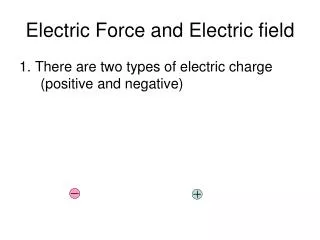
1 / 13
130 likes | 229 Views
Understand the control signals in computer architecture that determine the flow of data within the CPU. Explore how registers, memory, and ALU operations are managed through various signals. Get insights into instruction execution flow.

E N D
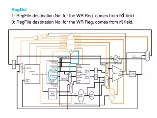
RegDst 1: RegFile destination No. for the WR Reg. comes from rdfield. 0: RegFile destination No. for the WR Reg. comes from rtfield.
RegWrite 1: general-purpose Reg. selected by the WR Reg. No. is written with the value of the WR data input. 0: None.
ALUSrcA 1: 1st ALU operand comes from Reg. A. 0: 1st ALU operand is the PC.
MemRead 1: Memory contents as the location specified by the address input is put on MDR. 0: None.
MemWrite 1: Memory contents as the location specified by the address input is replaced by the value on WR data input. 0: None.
MemtoReg 1: Value fed to the RegFile WR data input comes from MDR. 0: Value fed to the RegFile WR data input comes from ALUOut.
IorD 1: ALUOut is used to supply the address to the MEM. 0: PC is used to supply the address to the MEM.
IRWrite 1: Output of the MEM is written into the IR. 0: None.
PCWrite 1: PC is written; its source is decided by PCSource. 0: None.
PCWriteCond 1: PC is written if Zero output of ALU is 1. 0: None.
ALUOp 00: ALU performs add operation. 01: ALU performs subtract operation. 10: ALU operation determined by Func. field of instruction.
ALUSrcB 00: 2nd ALU input comes from Reg. B. 01: 2nd ALU input is constant 4. 10: 2nd ALU input is sign-extended 16 LSBs of IR. 11: 2nd ALU input is sign-extended 16 LSBs of IR, left shifted in 2 bits.
PCSource 00: Output of ALU (PC + 4). 01: ALUOut Reg. (branch target address). 10: Jump address (PC[31:28]IR[25:0]00).