Download
1 / 47
480 likes | 645 Views
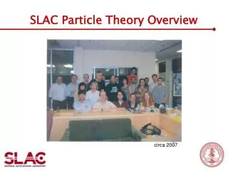
SLAC Timing System Overview. Mike Stanek SLAC Accelerator Dept. Operations Group 16-Sep-2003. SLAC Aerial View. SLAC Timing System Specifications. SLC Design: (~1982) Resolution: <10 nSec - Jitter: <1 nSec - RF distribution. PEP – II: (~1998) - Resolution: 2.1 nSec

E N D
SLAC Timing System Overview Mike Stanek SLAC Accelerator Dept. Operations Group 16-Sep-2003 SLAC Timing System Futures Workshop
SLAC Timing System Specifications • SLC Design: • (~1982) • Resolution: <10 nSec • - Jitter: <1 nSec • - RF distribution PEP – II: (~1998) - Resolution: 2.1 nSec - Jitter: 20 pSec SLAC Timing System Futures Workshop
Synchronization Requirements • AC Line Voltage • (2 zero crossings x 3 phase 60 hz = 360 hz) • Damping Ring RF bucket • (8.5 MHz revolution harmonic) • Linac Main Drive Line • (476 MHz) • PEP RF buckets • (3492 buckets, 136 KHz rev. harmonic) SLAC Timing System Futures Workshop
Devices • Klystron Modulator thyratrons • Pulsed kicker magnets • Beam diagnostics (BPM, Gated ADC’s, Toroids) • For devices requiring < 10 nsec precision, specialized hardware has been developed • TGAS (gun triggers) • Vernier Delay Unit – 100 psec (Damping Ring kickers) SLAC Timing System Futures Workshop
Fiducials (Master Clock pulses) • Linac – at 360 Hz • one “double amplitude” 476 MHz cycle inserted on Main Drive Line RF distribution • PEP-II • 360 Hz “injection” fiducial – sync’ed to Linac • 136 KHz “ring” fiducial – from PEP Master Oscillator (also locked to Linac M.O.) • One (two) “double period” cycle SLAC Timing System Futures Workshop
Waveforms: 476 MHz with FIDUCIALS LINAC PEP - 2 SLAC Timing System Futures Workshop
Trigger Generation, simplified SLAC Timing System Futures Workshop
Sector 0 Trigger Generation, oversimplified SLAC Timing System Futures Workshop
Trigger Generation, simplified 1 5 2 4 SLAC Timing System Futures Workshop 3
Linac Sector Timing • 476 MHz + fiducial coupled from MDL • Divide-by-four ( 119 MHz) • 8.4 nsec “ticks” (SLC specs) • Convert “double amplitude” fiducial to “missing cycle” of 119 MHz. • FIDucial Output chassis (FIDO) SLAC Timing System Futures Workshop
LINAC Timing Typical Sector Divide by 4 8.4 nsec ticks CAMAC SLAC Timing System Futures Workshop
LINAC Rack, Front SLAC Timing System Futures Workshop
LINAC Rack, Rear SLAC Timing System Futures Workshop
MDL Coupled Output SLAC Timing System Futures Workshop
Waveforms: 119 MHz and NIM Pulse FIDO Output PDU Output SLAC Timing System Futures Workshop
NLC Test Accelerator • Uses Linac Fiducials • Distributed to NLCTA via fiber optic link, from the downstream end of the Linac to the Research Yard. SLAC Timing System Futures Workshop
Fiber Optic Xmtr SLAC Timing System Futures Workshop
Fiber Optic Link SLAC Timing System Futures Workshop
NLCTA Triggers SLAC Timing System Futures Workshop
PEP-II fiducial generation • PEP-II uses two types of fiducials, generated in Region 8 • 360 Hz, sync’ed to Linac fiducials for injection • 136 KHz, sync’ed to PEP Master Oscillator for stored beam diagnostics and control • PEP Master Oscillator is (usually) locked to Linac Master Oscillator. SLAC Timing System Futures Workshop
PEP – II Timing Generation SLAC Timing System Futures Workshop
PEP-II timing distribution • PEP has 2 RF distribution cables: • One WITH the fiducial superimposed • One WITHOUT fiducial (used by the RF systems) • In each PEP IR hall, the Timing distribution signal is compared and phase locked to the “RF only” signal. SLAC Timing System Futures Workshop
PEP – 2 Timing Distribution SLAC Timing System Futures Workshop
Timing Phase Lock Distribution B.D. Graphic by E.L.Cisneros SLAC Timing System Futures Workshop
TPLD SCP Diagnostics 2 SLAC Timing System Futures Workshop
“Instructions” for each Fiducial • Master Pattern Generator (microprocessor) • uses SLCnet cable to send 126 bits (x3) every fiducial pulse to remote micros • “PNET” band of SLCnet • “Pipelined” bits for the next 3 fiducials • MSB a.k.a. Beamcode or PP (pulsed pattern) SLAC Timing System Futures Workshop
Each bit has designated purpose, e.g.: • BPM data acquisition for specific application • No beam (gun trigger suppress) • Use this pulse for e- feedback data • HER injection • Fire the HER Injection tune-up dump kicker SLAC Timing System Futures Workshop
MPG multi-tasking • Linac Klystron maximum rate is 120 Hz (only uses 1/3 of available fiducials) • Other 240 fiducials can be labeled for other programs (NLCTA, Gun Test lab) SLAC Timing System Futures Workshop
MPG bit patterns determined by inputs from… • Machine Protection Systems • Algorithm processor micros • Direct inputs from older hardware • BaBar – stop injection • Operator requests • PEP injection system (BIC) – which bucket to fill, and how much charge – shared memory SLAC Timing System Futures Workshop
What happens at a remote micro? • Interrupt the micro • Translate 126 bit word 8 bit word • Broadcast to CAMAC crates • PDU (Programmable Delay Unit) • Combines Analog (119 MHz + fiducial) with Digital (beamcode info) • 16 programmable countdown channels • Generate trigger on CAMAC upper backplane SLAC Timing System Futures Workshop
PDU flexibility • Each channel generates output trigger: • Adjustable over 2.7 msec range (8.4 nsec steps) • Or using (n-1) or (n-2) fiducial with pipeline info, that range can be shifted up to 5.4 msec early • On specific combinations of PNET bits • “On demand” for BPM data acquisition • (YY mode) • On every fiducial, independent of PNET bits • On a subset of fiducials (multiples of 10 hz) SLAC Timing System Futures Workshop
PDU – SLC Type Sixteen channels per PDU; One channel shown SLAC Timing System Futures Workshop
LINAC Timed Crate SLAC Timing System Futures Workshop
PEP micro & CAMAC • PEP PDU • Direct 476 MHz + fiducial input (2.1 nsec ticks) • Programmable for • Injection mode or Ring mode (136 KHz) • HER or LER • Continuous or Fixed length Pulse Train SLAC Timing System Futures Workshop
The combination of Micro code (both MPG and remote micros) and PDU (and VDU) modules • flexibility in generating triggers. SLAC Timing System Futures Workshop
An important feature: Synchronous data collection • BPM data can be acquired for a single e- pulse as it travels through the accelerator. • Correlation of Buffered BPM data (labeled with Pulse ID) can be used to make difficult measurements and diagnose accelerator instabilities. • Feedback systems can be “Cascaded”, to prevent overcorrection of errant trajectories. SLAC Timing System Futures Workshop
PEP RF bucket synchronization • Generate a specially timed Linac Fiducial for each PEP bucket (3492) • i.e. shift the entire Linac timing • Beam to be injected is already stored in the Damping Ring (8.3-16.6 msec store time) • Delaying the fiducial by “n” Damping Ring turns, we can hit 25% of the PEP buckets… SLAC Timing System Futures Workshop
How to figure out “n” ? • TPEP=3492 b476TDR=56 b476 =(4*9*97)b476 =(4*2*7)b476 • TPEP=(873/14)TDR • 14 TPEP= 873 TDR • By changing the number of stored DR turns we inject into 873 different PEP buckets. • (1/4 of total 3492) SLAC Timing System Futures Workshop
If the desired bucket number (D) is known, MPG can calculate number of DR turns (R) to wait. R= (D*686) mod 873 SLAC Timing System Futures Workshop
How is the shifted fiducial created? • PEP Trigger Generator (PTG) module in an injector CAMAC crate: • Input bits from MPG (over PNET) tell it how many DR turns to delay. • Line locked gate from SLC MTG module (873 TDR wide) • 476 MHz input (-> generates PEP bucket clock, period= 873 TDR) • Outputs fiducial pulse to SLC MTG for distribution on MDL. SLAC Timing System Futures Workshop
What about the other ¾ of PEP buckets? • While beam is stored in DR, shift Linac Master oscillator -1, or +1, or +2 buckets of 476 MHz. • 720 degree (476 MHz) Pulsed phase shifter in series with the Linac Master Oscillator. Programmed to shift phase based on special PNET bits from MPG. • DR extracted beam is locked to Linac RF – ramp phase slow enough to keep the beam stable SLAC Timing System Futures Workshop
Check to see if it worked… • Compare Linac fiducial with a PEP bucket 0 fiducial. (both signals are in MCC) • Difference should be predicted by MPG. • Time Difference Counter (TDC) circuit in injector PTG module, and in MPG crate. • MPG synchronization feedback. • MPG can correct for changes > 1 PEP bucket. • Can disable injection to PEP if not stable. SLAC Timing System Futures Workshop
RF signal degradation and noise Poor cable connections Sensitivity to temperature extremes Bucket “jumps” in PEP timing system One leg of the TDC comparison shifts wrt the other. Often the beam has not shifted – just the measurement, but feedback still applies a correction. Some Common Timing Problems
References • Thanks to Duane Thompson (retired) of ESD – • (I borrowed many of his Power Point slides) • SLAC-PUB-3508 A New Timing System for the Stanford Linear Collider • SLAC-PUB-3476 The Design of a Semi-custom Integrated Circuit for the • SLAC SLC Timing Control System • PEP-II Injection Timing and Controls • SLAC-PUB-4231 Timing Stabilization for the SLC Electron Source • SLAC-PUB-4906 Timing and RF Synchronization for Filling PEP/SPEAR with The SLC Damping Rings • IEEE Trns A Programmable Delay Unit Incorporating a Semi- Nucl. Sci. Custom Integrated (Circuit PDU Write-up) • NS-34, No. 5,2112 (1985) SLAC Timing System Futures Workshop
SLAC-CN-144 Pulse-to-Pulse Control of the LINAC with the new ControlsSystem • NSS 1984 A Vernier Delay Unit, W.B. Pierce • BD-135-730-NN SLC Timing System (update in progress, Oct 2001) • SLACSpeak http://www.slac.stanford.edu/spires/slacspeak/ • Principles Of OPeration • http://www.slac.stanford.edu/grp/cd/soft/wwwman/poop.html • Basic Users Guide • http://www.slac.stanford.edu/grp/cd/soft/wwwman/bug.www/ • SLC Hardware Manual • http://www.slac.stanford.edu/grp/cd/soft/wwwman/hard.www/ SLAC Timing System Futures Workshop