Download
1 / 1
20 likes | 170 Views
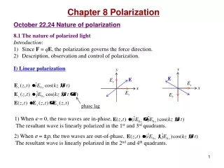
Building a Photodetector to Observe the Polarization of Light Kevin J. McElwee Bridgewater State University, Bridgewater MA 02325 Mentor: Edward F. Deveney Ph.D. Introduction

E N D
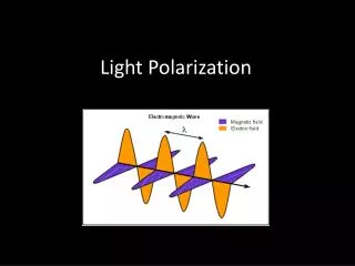
Building a Photodetector to Observe the Polarization of Light Kevin J. McElwee Bridgewater State University, Bridgewater MA 02325 Mentor: Edward F. Deveney Ph.D. • Introduction • Light is an electromagnetic wave that travels through space. Many light sources, such as a lamp or the sun, emit unpolarized light; that is, the electromagnetic waves do not oscillate in a single plane, but rather multiple planes. In this experiment, we created a photodetector, which was used to measure the output voltages as we changed the orientations of our two linear polarizing filters when laser light passed through them. Our photodetector converted light into current. From that current, we measured the voltage across a resistor. Thus, we were able to measure how the voltage changed as we rotated our filter and compared it to existing theory. • What is Polarized Light? • Using Maxwell’s equations, one can show that light Is a transverse electromagnetic wave composed of an oscillating electric field, which gives rise to an oscillating magnetic field, which then gives rise to an oscillating electric field and so on. • Figure 1: An oscillating electric field gives rise to an oscillating magnetic field and vice versa. As a result of this, Maxwell’s equations show that light is composed of both of these waves that travel at the speed of light. • When referring to the polarization of light, one must look at the plane in which the electric field oscillates in (plane-of-vibration). In the examples below, assume there are separate optical disturbances (Ex and Ez), which demonstrate different polarizations of light. • With Linearly Polarized Light, two electric field disturbances are either in phase or 180° out of phase. This way, the electric field oscillates in one plane. • Figure 2: Above, two electric fields (Ex and Ez components) oscillate in separate planes (y-z plane and x-y plane). When added together, the magnitude of the vector-summed wave oscillates between a minimum and maximum value and its direction points at 45° or 225° with respect to the x-axis. • With Circularly Polarized Light, two electric field disturbances are 90° out of phase. This way the electric field oscillates with the same magnitude in all directions from 0° to 360°. They can oscillate right circularly or left circularly. • Figure 3: Above, two electric fields (Ex and Ez components) oscillate in separate planes (y-z plane and x-y plane). When added together, the magnitude of the vector-summed wave is constant, while the direction varies between 0° and 360°. • How Do We Polarize Light? • In this experiment we produced polarized light by using linear polarizing filters. • Nonpolarized light will oscillate in all directions. One type of linear polarizing filter, a polaroid filter, is composed of long chains of parallel molecule strands. These strands will only absorb the energy from a specific plane-of-vibration. • Figure 4: The concept of a filter “selecting” certain components of light to pass through, is analogous to creating a wave with rope and sending it through a picket fence. • When two filters are introduced, the first filter passes through the component of light that is in line with the transmission axis of the filter. Light will only pass through the second filter (analyzer) if the polarized light from the first filter had a component of the electric field that was in line with the transmission axis of the second filter. • The Law of Malusshows how the irradiance of light changes as the orientation of the second filter changes with respect to the first filter. • I0 is the incident irradiance just as it reaches the second filter. The angle, θ, represents the angle that the second filter has turned with respect to the first filter. • Experimental Setup • We used a Newport HeNe 633 nm, 1.5 mW laser in our experiments. Our laser emits unpolarized light. • We setup our experiment on an optical breadboard as shown below: • Figure 5: BSA devices represent our beam steering assemblies. LP #1 and LP #2 represent our linear polarizers, numbers one and two, respectively. We built our photodetector since it was not supplied to us. • Figure 6: The above circuit produced in Multisim 11.0, shows the circuitry of our photodetector. • The phototransistor converts light energy into electrical energy. This electrical energy takes the form of current (photocurrent). • As more light hits the phototransistor, more photocurrent passes through the circuit. • We measured the voltage across the resistor in the circuit. As more current passed through the resistor, a stronger voltage was measured across the resistor. We measured the output voltage using a multimeter (or simply a voltmeter); as more light hit the phototransistor, a higher voltage was ready by the multimeter. • Results & Discussion • Our multimetermeasured the voltage across the resistor, which was proportional to the irradiance of light that hit the phototransistor; therefore, its graph will plot theta vs. voltage. • The theory graph plots theta vs. irradiance. Both graphs produce the same shape, however. Adjusting the magnitude of I0 allows us to compare data with our theory. We held the first filter in place, while turning the analyzing filter 180°. • Figure 7: A phase shift exists between our theory and data. This is because the transmission axis of our first filter and analyzer filter were not perfectly aligned when we began to collect data. Theta measures the angle of the analyzer’s transmission axis with respect to the transmission axis of LP #1. The error has been amplified by 600% for visual purposes. • Standard deviations from multiple trials of data collection were used to produce error. • Even if the superimposed data were in phase with each other, the shapes of each resemble one another, but not very well. This could be due to mode sweeping of our laser (our laser has three polarization modes), which significantly affected to the output voltages read by our multimeter. • Conclusion • We observed the wave-like properties of light when performing this experiment. In doing so, we observed linearly polarized light by sending light through two separate linear polarizing filters and altering the transmission axis of our analyzer. • We used a phototransistor to build a photodetector, which measured the power of our laser after passing through two linear polarizing filters. • Acknowledgements • I would like to thank Dr. Deveney for purchasing the materials required to build the photodetector for this experiment.