Download
1 / 17
170 likes | 326 Views
A Unified Model-based Systems and Software Engineering Approach to ISHM. Michel Ingham, Gregory Horvath, David Wagner Jet Propulsion Laboratory, California Institute of Technology

E N D
A Unified Model-based Systems and Software Engineering Approach to ISHM Michel Ingham, Gregory Horvath, David WagnerJet Propulsion Laboratory, California Institute of Technology Oliver Martin, Seung Chung, Paul Elliott, Brian WilliamsComputer Science and Artificial Intelligence Laboratory, MIT ISHEM Workshop 11/09/2005
Motivation • Spacecraft operate in a harsh, uncertain environment. • Spacecraft achieve robustness by managing a complex set of redundant subsystems, over a range of possible nominal and off-nominal scenarios. • Reasoning about interactions within and between subsystems during sensing and actuation is complex and error-prone, and requires significant interaction between systems engineers and software programmers. • The traditional gap between systems and software engineering can lead to errors that manifest themselves as software defects. • NASA software engineering practice has been challenged to create and verify space systems that assure correctness, reliability, and robustness in a timely and cost effective manner.
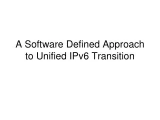
Blah blah SHALL not do (TBD) or whatever … blah blah blah ERROR . . . ERROR . . . ERR OR . . . ERROR . . . ERROR . . . ERROR . . . ERROR . . . ER ROR . . . ERROR . . . ERROR . . . ERROR . . . ERROR . . . E RROR . . . ERROR . . . ERRO R . . . ERROR . . . ER Bezillions of lines of pure gobbledy gook full of arcane jargon that no one understands, but it sure looks impressive 2 E = m c doesn't it? Objective/Vision Current Practice: System Software is a Surrogate for Systems Engineers, and Software Engineers perform the transformation. Our Goal: Models from Systems Engineers are provided directly to the embedded system, which is capable of reasoning through them to accomplish mission objectives and manage the health of the system!
Approach • The State-of-the-Art is still far from fully achieving this Vision • Yet even incremental steps toward this Vision can greatly improve on the current practice, producing software that is: • Less error-prone, • More robust to off-nominal situations, • Three facets of our approach: • Develop representations and algorithms that endow the embedded system with the requisite reasoning capabilities (Model-based Programming and Execution) • Integrate these technologies into a principled software architecture that facilitates adaptation to a particular application (State-based control architecture and MDS software framework) • Provide Systems Engineers with methods and tools that help them reason through the system design and develop models in a rigorous way (State Analysis) • Cheaper, • Easier to verify, etc…
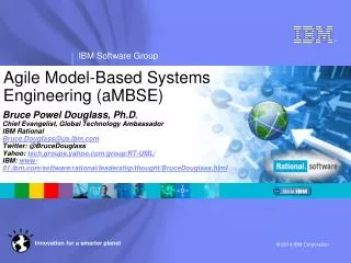
State Analysis • A uniform, methodical, and rigorous approach for… • Discovering, characterizing, representing, and documentingthe states of a system • Modeling the behaviorof states and relationships among them, including information about hardware interfaces and operation • Capturing the missionobjectives in detailed scenarios motivated by operator intent • Keeping track of system constraints and operating rules, and • Describing the methods by which objectives will be achieved • For each of these design aspects, there is a simple but strict structure within which it is defined… Battery State of Charge Measurements Heater Switch Measurements state state effect An exampleState EffectsDiagram command data state RTG Output Current Battery State of Charge data effect Heater Switch Status and Health Heater Switch Commands Heater Power Use independent state independent state Available Power RTG Output Current Measurements Module Temperature External Temperature Module Temperature Measurements derived effects Power Margin measurement data state derived state (dependent state)
Msmt: Ant_N Pointing Cmd: Ant_N Mech D.S. Target Signal State Msmt: Ant_N Motor Current Offline & not ready Repaired msmt Offline & ready Simple: Background & Noise Signal State Msmt: Ant_N Received Signal Go offline cmd Come online cmd Tracking On-pnt msmst Simple: Ant_N Mech OpMode & Health On-pnt Shutdown Power off Stowing Power off Off-pnt Received Signal 1: Target Signal present Off-pnt msmt Power off Go to Stowed Stowed or go-idle Begin Tracking Power on Msmt: Ant_N Mech OpMode Idle End-of-profile or go-idle Simple: Ant_N Received Signal Received Signal 1: Transition to Target Signal Present Received Signal 1: Is Known If Ant_N Mech OpMode & Health = not shutdown or offline if Target Signal State = present and Ant_N Mech OpMode & Health = on-point then: Target + Noise + Background else: Noise + Background Ant_N Mech OpMode & Health: Healthy, Tracking & On-point Ant. N Mech.State Variable StateValues StateFunctions Msmt: Ant_N Mech Power Cmd: Signal Inclusion D.S. Target Signal: Always Present Models Msmt: Correlationmatrix Noise & Background: Unconstrained Ant. N Mech.Controller Ant. N Mech.Estimator Min to Max Commands Measurements& Commands Ant. N Hardware Adapter Msmt: Signal Weights Min to Max Goal Simple: Array SP Correlator & Combiner State Msmt: Array Correlator Power Supporting Goal Simple: Combined Signal State Msmt: Combined Signal SNR Supporting Goal Supporting Goal Supporting Goal Supporting Goal Overview of State Analysis 2. State Analysis produces model 1. System to be controlled 3. Model informs software design 4. Model informs operations
Mission Planning & Execution ControlGoals KnowledgeGoals State Knowledge StateValues StateFunctions Models StateControl StateEstimation System Under Control Commands Measurements& Commands Hardware Adapter Sense Act State-based Control Architecture Explicit state variables System operation via overt, objective statements of intent Clear delineation between control system and system under control Models inform all aspects of control system Separation of estimationfrom control; diagnosis and recovery are integrated with nominal execution
Mission Planning & Execution KnowledgeGoals ControlGoals State Knowledge StateValues StateFunctions Models Scenario Fragments GEL State Query Visualization Simulation Scheduler StateControl StateEstimation Goals Time State Knowledge Goal Achiever: Goal Network H/w Adapter Graph State Variable Measurements Commands Measurements& Commands Hardware Adapter Estimators State Constraints Sense Components/Connectors Value History Data Catalog Data Transport Act Controllers Various Models EWS/EWC ELF Naming Time DM/DT/Policy CCSDS Resources State Variables Commands Allocations Initialization Serialization Exception Graph Physics: Math Estimation Utility Time Constraints System Under Control C++ Standard Library Unit Testing RTOS ACE Bridging the Gap betweenSystems & Software Engineering State Analysis:Model-based Requirements Map Directly to Software • Common VocabularyReduces Errors of Translation
Embedded Program Model-basedEmbedded Program Obs Cntrl Estimated State Model-based Executive State Plant Obs Cntrl State Plant Model-based Programming • Embedded programs interact withthe system’s sensors/actuators: • Read sensors • Set actuators • Model-based programs interact with the system’s (hidden) state directly: • Read state • Set state Model-based Executives automatically reason through interactions between states and sensors/actuators. Programmers must reason through interactions between state and sensors/actuators.
Mission Planning & Execution ControlGoals KnowledgeGoals State Knowledge StateValues StateFunctions Models StateControl StateEstimation System Under Control Commands Measurements& Commands Hardware Adapter Sense Act Integrating Model-based Programmingand Execution into the Architecture Models are used EXPLICITLY by the control system Model-based reasoning algorithms to compute a series of commands that progress the system towards a least-cost state that achieves the goal. • Model-based reasoning algorithm: • Tracks a limited set of most-likely states • Explores state space in best-first order Configuration Goals Goal State Command Reactive Planner Goal Interpreter Current State
off- cmd standby- cmd 0.01 fire- cmd standby- cmd 0.01 Model Representation: PCCA (Variant of Factored POMDP) and cost/reward with deterministic and probabilistic transitions… component modes… described by finite domain constraints on variables… Engine Model Camera Model (thrust = zero) AND (power_in = zero) Off Resettable Off 0.01 (power_in = zero) AND (shutter = closed) Failed (thrust = zero) AND (power_in = nominal) 0.01 turnon- cmd turnoff- cmd Standby reset- cmd (power_in = nominal) AND (shutter = open) (thrust = full) AND (power_in = nominal) On Firing one per component … operating concurrently
t t+1 Estimation Using PCCA Models • PCCA system model is compiled into a form suitable for reasoning (propositional logic) • Belief State evolution visualized with a Trellis Diagram • Complete history knowledge is captured in a single belief state by exploiting the Markov property • For each estimation cycle, belief states are computed using the HMM belief state update equations:
consistent with model & obs? most-likely candidate most-likely state estimate conflicts (infeasible modes) conflict-directedbest-first search conflict database Computationally TractableState Estimation & Fault Diagnosis • Recast Belief State Update problem as an Optimal Constraint Satisfaction Problem (OCSP) • Solve using OPSAT engine: • The belief state can be accurately approximated by maintain the k most likely estimates • The probability of each state can be accurately approximated by the most likely trajectory to that state • The observation probability can be reduced to • 1.0 for observations consistent with the state, • 0.0 for observations inconsistent with the state Approximations to Estimation Assumptions made by Livingstone, Livingstone-2 Assumptions relaxed by Titan Model-based Executive
Diagnostic Algorithm Performance • Two primary concerns regarding application of model-based reasoning onboard spacecraft are processor throughput and memory limitations • To address this concern, we have evaluated the performance of Titan’s state estimation capability in terms of estimation time and static/heap memory utilization • Variety of models (up to subsystem-size) • Variety of nominal and off-nominal scenarios (auto-generated)
Goal Goal Open On Off Closed Current Current idle cmd = off idle driver = on cmd = close Open On cmd = on idle driver = on cmd = open idle Closed Off cmd = reset cmd = off fail fail Stuck Resettable Computationally Tractable State Control & Fault Recovery INPUT • Current State • Tank = full • Pressure = nominal • Driver = off • Valve = closed • Thruster = off • Configuration Goal • Thrust = on OUTPUT • Goal State • Tank = full • Pressure = nominal • Driver = off • Valve = open • Thruster = on Configuration Goals Goal Interpreter Goal State Current State OPSAT is used to generate optimal goal state that achieves the Configuration Goal! INPUT • Current State • Tank = full • Pressure = nominal • Driver = off • Valve = closed • Thruster = off • Goal State • Tank = full • Pressure = nominal • Driver = off • Valve = open • Thruster = on OUTPUT • Command • Turn driver on Command Reactive Planner Goal State Ensures progress toward the goal state, only generates non-destructive actions, never proposes actions that lead to dead-end plans, and operates at reactive time scale. Current State
Continuous state: flow x Discrete modes closed part. open open stuck closed stuck open Flow Regulator Next Steps • Demonstrate integrated architecture and approach on scaled-up system • Accommodate other modeling representations and estimation algorithms, e.g., hybrid systems (discrete modes with continuous dynamics) • Elevate deliberative ISHM capabilities by integrating planning & scheduling based on same models • Develop formal V&V approach for model-based programs • probabilistic analysis of possible system executions • lead to verifiably-correct system behavior for both nominal and off-nominal execution • focus on specific validation needs of future NASA exploration missions Proposed DSN Array