Download
1 / 12
120 likes | 149 Views
Explore the operation and regions of Metal-Oxide-Semiconductor Field-Effect Transistors (MOSFETs) in engineering. Learn about silicon properties, insulator conductors, and polarity types. Understand the operating regions critical to electronic design and circuit performance.

E N D
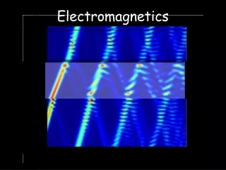
Engineering Electromagnetics 10909.301.01Fall 2004 INTRODUCTION TO MOSFETSOctober 6, 2004 Linda Head ECE Department Rowan University http://engineering.rowan.edu/~shreek/fall04/eemag1/lectures/mosfets.ppt
h+ e - Si Si Si Si Si Si Si Si Si Si Si Si Si B- Si h+ h+ e - e - h+ e - + Ph Silicon - Four Cases Intrinsic Si - 0oK Intrinsic Si - Room Temp N-type Si P-type Si
Metal SiO2 p-type silicon n+ polysilicon Metal-Oxide-SemiconductorCapacitor
Insulator Conductor Conductor Looks Like…….
SiO2 +V Gnd. p-type Si Metal and Polysilicon The positive charge on the metal is matched by negative charge from the ions in the p-type semiconductor. The h+ just get pushed away from the interface between the insulator and the p-type semiconductor leaving only the “stuck” charged atoms. We call this the depletion region - we now have a 2-layer insulator.
SiO2 ++V Gnd. p-type Si Electron Channel Metal and Polysilicon Once a maximum width is reached for the “depletion region” the electrons in the material are attracted to the SiO2 / p-type Si interface and now there is an channel of electrons right underneath the SiO2
Al n+ Polysilicon Al Al Si Si Si Depletion Region 0.4 V 0 V
Inversion Region 0 V 1.0 V 0 V
Linear Region 1 V 0.25 V
Pinch-Off Region 1 V 1.5 V
Things You Need To Know • r(Si) = 11.8 r(SiO2) = 3.9 • The length of the “channel” is 1. • The n+ source and drain, the polysilicon and the p+ semiconductor are metal-like conductors.