Download
1 / 5
50 likes | 159 Views
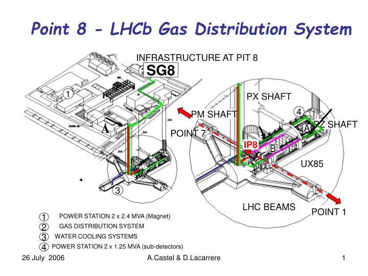
Point 8 - LHCb Gas Distribution System. INFRASTRUCTURE AT PIT 8. SG8. 2. 1. PX SHAFT. 4. PM SHAFT. PZ SHAFT. A. A. POINT 7. IP8. B. UX85. 3. LHC BEAMS. POINT 1. 1. POWER STATION 2 x 2.4 MVA (Magnet). 2. GAS DISTRIBUTION SYSTEM. 3. WATER COOLING SYSTEMS. 4.

E N D
Point 8 - LHCb Gas Distribution System INFRASTRUCTURE AT PIT 8 SG8 2 1 PX SHAFT 4 PM SHAFT PZ SHAFT A A POINT 7 IP8 B UX85 3 LHC BEAMS POINT 1 1 POWER STATION 2 x 2.4 MVA (Magnet) 2 GAS DISTRIBUTION SYSTEM 3 WATER COOLING SYSTEMS 4 POWER STATION 2 x 1.25 MVA (sub-detectors) A.Castel & D.Lacarrere
LHCb Gas Distribution – Brief Status • SG8 GAS BUILDING • Re-connection of gas pipes (ex-DELPHI) – CEGELEC - ATEFLUID • Refurbishment of gas panels (pneumatic valves): CO2, N2, Ar & Ar/H2 • New panels : Premix OT & Premix MUON • Calibration lines & panels (4) from flammable gas room up to gas mixture room. • Installation of a new exhaust (45 mm diameter) in gas mixture room • Tests of gas pipes : Radiography (Gamma-rays) of the welds (10% horizon. position) • + Pressure tests (10 b – pressure design) – pressure operation 5-6 b • Re-connection of Dewars (Ar & N2) : painting, vacuum insulation, pressure tests UNDERGROUND UX85 (up to the control racks – Zone A) Re-connection of gas pipes (ex-DELPHI) • New lines from are UXA C3 to UXA A3. • Radiography (gamma-rays) 0f welds (10% horizontal position – 100% vertical) • Pressure tests of the gas pipes CONCLUSIONS Inert gases (CO2, Ar & N2) are now available at the platform UXA A3 & UXA C3 Other gases (premix , CF4, C4F10) will be available by end of August 2006 A.Castel & D.Lacarrere
Point 8 - LHCb Gas Pipes – Radiography (Gamma-rays) INFRASTRUCTURE AT PIT 8 5 SG8 2 1 4 PX SHAFT 1 3 4 PM SHAFT PZ SHAFT A A POINT 7 IP8 B UX85 2 3 1 – SD8 – Top of the PM85 Shaft 2 – US85 – Bottom of the PM85 3 – UX85 – RB84 Side – level of gangway of cranes 4 – UX85 – RB86 Side – level of gangway of cranes 5 – SG8 – Gas Building - Surface. LHC BEAMS POINT 1 1 POWER STATION 2 x 2.4 MVA (Magnet) 2 GAS DISTRIBUTION SYSTEM 3 WATER COOLING SYSTEMS 4 POWER STATION 2 x 1.25 MVA (sub-detectors) A.Castel & D.Lacarrere
AREAS 3 4 5 6 7 8 9 10 11 12 13 14 15 16 17 18 19 20 21 23 22 1 - SD8 2 - US85 3 - UX85 – RB84 4 - UX85 – RB86 5 -SG8 Point 8 - LHCb Gas Pipes – Radiography (Gamma-rays) – Planning (20:00 – 2:00) July 2006 WEEK 29 WEEK 27 WEEK 28 ACHIEVED A.Castel & D.Lacarrere
Remaining Works • SG8 GAS BUILDING • Installation of a new Dewar for Liquid CO2 (6000 l) – rental = 10-15 kCHF/year • Installation compressor for recovering CF4 • Connection and putting in operation cooling unit (compressor) • Safety - Complete check of all pressure equipments (with SC) UNDERGROUND UX85 (Zone A to Zone B) New gas piping from A to B (CRIOTEC – ongoing) up to the gantry (RB86 side) • Installation of gas pipes on the gantry up to the bunker (September 06) • Exhausts • Radiography (gamma-rays) of welds • Pressure tests of the gas pipes A.Castel & D.Lacarrere