Download
1 / 72
0 likes | 11 Views
Voyager-SAN-Cluster_12-bay-2U-RAID_SetupGuide

E N D
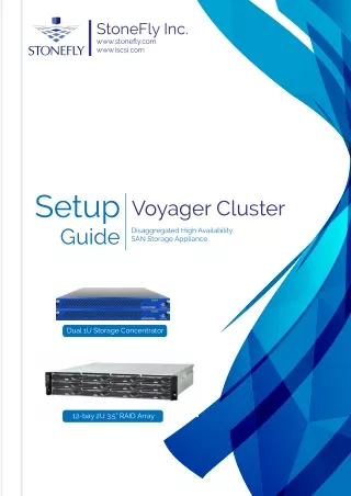
StoneFly Inc. www.stonefly.com www.iscsi.com Setup Guide Voyager Cluster Disaggregated High Availability SAN Storage Appliance Dual 1U Storage Concentrator 12-bay 2U 3.5” RAID Array
This Page is intentionally left blank. Page 1 V8.0.3x © StoneFly Inc. | All rights d
Voyager Cluster Appliance Setup Guide Copyright © 2006-2019 StoneFly, Inc. All rights are reserved. No part of this document may be photocopied or reproduced without the prior written consent of StoneFly. The information contained in this document is subject to change without notice. StoneFly shall not be liable for errors contained herein or for consequential damages in connection with the furnishing, performance, or use of this material. StoneFly, the StoneFly logo, Storage Concentrator, Integrated Storage Concentrator, ISC, Modular Storage Concentrator, StoneFly Backup Advantage, StoneFusion, StoneFly Replicator CDP, ValueSAN, Unified Scale Out, USO, Super Scale Out, SSO, Twin Scale Out, TSO, Unified Storage & Server, USS, Unified Deduplicated Storage, UDS, Unified Encrypted Storage, UES, OptiSAN, StoneFly Voyager, DR365, DR365 Fusion, StoneFly Mirroring, Storage Concentrator Virtual Machine, SCVM, Software-Defined Unified Storage, SDUS, and StoneFly Cloud Drive are property of StoneFly, Inc. Other brands and their products are trademarks or registered trademarks of their respective holders. Page 2 V8.0.3x © StoneFly Inc. | All rights d
Voyager Cluster Appliance Setup Guide Table of Contents 1.1 Introduction .......................................................................................................................... 5 1.1.1 Icons .......................................................................................................................... 7 1.1.2 System Diagram & Description .................................................................................... 7 1.1.3 Product Registration.................................................................................................. 8 1.1.4 Contacting StoneFly for Help ................................................................................... 8 2.1 Mounting the Equipment ................................................................................................... 10 2.1.1. 1U Storage Controller Rack Installation Instructions ................................................. 10 2.1.2. 2U Storage Controller Rack Installation Instructions ................................................. 14 2.1.3. 2U RAID Array Rack Installation Instructions .......................................................... 19 Safety Reminders .................................................................................................................. 25 3.1 Cabling the Equipment ...................................................................................................... 27 4.1. RAID Array IP Address Configuration ............................................................................. 31 4.2 Serial Port Setup ................................................................................................................ 32 4.3 Web GUI IP Address Setup ............................................................................................... 35 4.4 Configuring IPMI KVM .................................................................................................... 37 4.5 Configuring the Network Settings for the Management Port ............................................ 42 4.6 StoneFusion™ Software Configuration ............................................................................. 43 4.7 Setting up Routing ............................................................................................................. 49 4.8 Confirming Setup ............................................................................................................... 50 4.8.1 Steps to Complete Before Setting Up the System: ..................................................... 51 4.9 Attaching and Removing the Front Bezel .......................................................................... 51 Page 3 V8.0.3x © StoneFly Inc. | All rights d
Introduction Voyager Cluster Appliance Setup Guide Chapter-1: Introduction Page 4 V8.0.3x © StoneFly Inc. | All rights d
Introduction Voyager Cluster Appliance Setup Guide 1.1Introduction This document is aimed for system administrators looking to get started with StoneFly Voyager cluster appliances. It briefly describes the initial steps for installing and launching the SAN cluster appliance. StoneFly Voyager cluster appliances are disaggregated high availability Storage Area Network (SAN) appliances with standard iSCSI support and an optional upgrade for Fibre Channel (FC). The StoneFly Voyager is an enterprise-grade block storage with integrated data services such as synchronous replication, encryption, delta-based snapshots, and many others along with optional upgrades such as deduplication, asynchronous replication, volume encryption, etc. This guide gives an overview of the hardware and software installation processes including Rackmount installation, appliance cabling, iSCSI-host connections, hybrid-host connections, network configuration, and software configuration. StoneFly Resource Library: https://stonefly.com/resources StoneFly Voyager cluster appliance webpage: https://stonefly.com/storage/san-storage A standard Voyager cluster appliance consists of three or more hardware chassis. •Dual 1U Storage Controller •Dual 2U Storage Controller •RAID Array For further expansion, the Voyager cluster appliances support expansion units (EBODs) available in 12 to 108-bay form factors. Supported Storage Controllers: 12Gb SAS (Voyager-DX): •Dual 1U Storage Concentrator Cluster Quad 12Gb SAS Connection •Dual 2U Storage Concentrator Cluster, Quad 12Gb SAS Connection 16Gb Fibre Channel (Voyager-FC): •Dual 1U Storage Concentrator Cluster, Quad 16Gb FC Connection •Dual 2U Storage Concentrator Cluster, Quad 16Gb FC Connection Dual 1U Storage Concentrator (with bezel) Page 5 V8.0.3x © StoneFly Inc. | All rights d
Introduction Voyager Cluster Appliance Setup Guide Supported RAID Arrays: 12Gb SAS RAID array: •12-bay / 2U 12Gb SAS HA RAID Storage Expansion Array (12 x 3.5” SAS drives) •16-bay / 3U 12Gb SAS HA RAID Storage Expansion Array (16 x 3.5” SAS drives) •24-bay / 4U 12Gb SAS HA RAID Storage Expansion Array (24 x 3.5” SAS drives) •24-bay / 2U 12Gb SAS HA RAID Storage Expansion Array (24 x 2.5” SAS drives) 16Gb FC RAID array: •12-bay / 2U 16Gb FC HA RAID Storage Expansion Array (12 x 3.5” SAS drives) •16-bay / 3U 16Gb FC HA RAID Storage Expansion Array (16 x 3.5” SAS drives) •24-bay / 4U 16Gb FC HA RAID Storage Expansion Array (24 x 3.5” SAS drives) •24-bay / 2U 16Gb FC HA RAID Storage Expansion Array (24 x 2.5” SAS drives) 12-bay 2U 3.5” 12Gb SAS / 16Gb FC RAID Array Supported expansion units (12Gb SAS): •12-bay / 2U 12Gb SAS HA Expansion Unit (12 x 3.5” SAS drives) •16-bay / 3U 12Gb SAS HA Expansion Unit (16 x 3.5” SAS drives) •24-bay / 2U 12Gb SAS HA Expansion Unit (24 x 2.5” SAS drives) •60-bay / 4U 12Gb SAS HA Expansion Unit (60 x 3.5” SAS drives – one drawer) •60-bay / 4U 12Gb SAS HA Expansion Unit (60 x 3.5” SAS drives – two drawers) •90-bay / 4U 12Gb SAS HA Expansion Unit (90 x 3.5” SAS drives) •108-bay / 4U 12Gb SAS HA Expansion Unit (108 x 3.5” SAS drives) Page 6 V8.0.3x © StoneFly Inc. | All rights d
Introduction Voyager Cluster Appliance Setup Guide 1.1.1Icons Icon Type Description Note Special instructions or information Warning Risk of system damage or a loss of data 1.1.2System Diagram & Description The figure below is an architecture diagram for StoneFly voyager cluster appliances comprising of two Storage Controllers (SC), and a shared RAID array with integrated dual active/active RAID controller. StoneFly Voyager Disaggregated High Availability Architecture Page 7 V8.0.3x © StoneFly Inc. | All rights d
Introduction Voyager Cluster Appliance Setup Guide 1.1.3Product Registration To initiate StoneFly customer service for your product, you must first register the appliance. Send us an email with the following information: Model Number: ______________ ____________________ Serial Numbers: Your appliance serial numbers start with D500 and are located on the rear of each chassis. 1.1.4Contacting StoneFly for Help Please have the following information available when contacting StoneFly technical support for assistance: Model Number: _____________________ ___________________________ Serial Number(s): D500 _ _ _ _ Software Version: ____________________ __________________________ Initiators: ___________________ ____________________ Storage: ___________________ _____________________ To contact StoneFly call 510.265.1616 (Select support from the menu). Our technical support is available 24 hours a day and 7 days a week. You can also contact us via email at support@stonefly.com Page 8 V8.0.3x © StoneFly Inc. | All rights d
Initial Installation Voyager Cluster Appliance Setup Guide Chapter-2: Initial Installation Page 9 V8.0.3x © StoneFly Inc. | All rights d
Initial Installation Voyager Cluster Appliance Setup Guide 2.1Mounting the Equipment This chapter includes steps to help install: •1U Storage Controller Rackmount •2U Storage Controller Rackmount •2U RAID Array Rackmount Depending on your chosen configuration, the Voyager cluster appliances can be configured with SAS connection (Voyager-DX) or FC connection (Voyager-FC) with support for 1776 drives (1U controller) or 4440 drives (2U controller) or more with FC switch (applicable only to Voyager-FC). For easier cabling and management, it’s recommended that the dual 1U storage controllers (or the dual 2U storage controllers) are mounted closer to each other and the 2U RAID array. To ensure proper installation and functionality of the StoneFly appliance, please observe the following warnings: •Wear an anti-static wristband before and during the installation procedure. •It is recommended to plug the system into two different power sources (eg. into a power outlet and another into a UPS). •Ensure the rack which the enclosure will be mounted onto has proper grounding and over-current protection. •Do not obstruct ventilation openings; provide 20cm of free space at the front and back of the enclosure for air circulation; keep the ambient temperature below 35 degrees Celsius. 2.1.1.1U Storage Controller Rack Installation Instructions This section provides information on installing the 1U storage controller appliance(s) into a rack or cabinet with the rails provided. There are a variety of rack/cabinet units on the market, which may mean that the assembly procedure will differ slightly. You should also refer to the installation instructions that came with the rack unit you are using. NOTE: This rail will fit a rack/cabinet between 25.6" and 33" deep. Identifying the Sections of the Rack Rails The StoneFly appliance chassis package includes two sets of rack rails, one set for the right side of the chassis and one for the left. Each set consists of an inner rail that is pre-attached to the chassis, an outer rail that attaches to the rack, and a middle rail that slides forward in the outer rail. Page 10 V8.0.3x © StoneFly Inc. | All rights d
Initial Installation Voyager Cluster Appliance Setup Guide Identifying the Sections of the Rack Rails Installing the Outer Rails onto the Rack Each end of the assembled outer rail includes a bracket with square pegs to fit into your rack holes. If you have an older rack with round holes, these brackets must be removed, and you must use screws to secure the rail to the rack. Outer Rail Installation 1.Align the square pegs on the front end of the rail with the square holes on the front of the rack (C). Push the rail into the rack until the quick release bracket snaps into place, securing the rail to the rack. Keep the rail horizontal. 2.Adjust the rail to reach just past the full depth of your rack. 3.Align the square pegs on the rear end of the rail to the holes on the rack (D) and push the rail into the rack until the quick release bracket snaps into place, securing the rail to the rack. Page 11 V8.0.3x © StoneFly Inc. | All rights d
Initial Installation Voyager Cluster Appliance Setup Guide Installing the Outer Rails to the Rack Note: The figure above is for illustrative purposes only. Always install servers at the bottom of the rack first. Stability Hazard: The rack stabilizing mechanism must be in place, or the rack must be bolted to the floor before you slide the unit out for servicing. Failure to stabilize the rack can cause the rack to tip over. Installing the Chassis into a Rack Once rails are attached to the chassis and the rack, you can install the server. 1.Pull the middle rail out of the front of the outer rail and make sure that the ball bearing shuttle is locked at the front of the middle rail. 2.Align the rear of the chassis rails with the middle rails and then push evenly on both sides of the chassis until it clicks into the fully extended position. 3.Depress the locking tabs on both sides of the chassis and push the chassis fully into the rack. The locking tabs should "click". 1.Thumb screws may be used to secure the front of the chassis to the rack. Page 12 V8.0.3x © StoneFly Inc. | All rights d
Initial Installation Voyager Cluster Appliance Setup Guide Installing the Chassis into a Rack Note: Keep the ball bearing shuttle locked at the front of the middle rail during installation. Note: Figure is for illustrative purposes only. Always install servers to the bottom of a rack first. Removing the Chassis from the Rack Caution! It is dangerous for a single person to off-load the heavy chassis from the rack without assistance. Be sure to have sufficient assistance supporting the chassis when removing it from the rack. Use a lift. If necessary, loosen the thumb screws on the front of the chassis that hold it in the rack. Pull the chassis forward out the front of the rack until it stops. Press the release latches on each of the inner rails downward simultaneously and continue to pull the chassis forward and out of the rack. Page 13 V8.0.3x © StoneFly Inc. | All rights d
Initial Installation Voyager Cluster Appliance Setup Guide Removing the Chassis from the Rack 2.1.2.2U Storage Controller Rack Installation Instructions This section provides information on installing the 2U storage controller in a rack unit with rack rails provided. There are a variety of rack units on the market, so the assembly procedure may differ slightly. Refer to the installation instructions that came with your rack. Note: This rail will fit a rack between 26.8” and 36.4”. Identifying the Sections of the Rack Rails The chassis package includes two rail assemblies. Each assembly consists of three sections: An inner rail that secures directly to the chassis, an outer rail that secures to the rack, and a middle rail which extends from the outer rail. These assemblies are specifically designed for the left and right side of the chassis. Page 14 V8.0.3x © StoneFly Inc. | All rights d
Initial Installation Voyager Cluster Appliance Setup Guide Identifying the Outer Rail, Middle Rail, and Inner Rail (Left Assembly Shown) Releasing the Inner Rail Each inner rail has a locking latch. This latch prevents the appliance from coming completely out of the rack when the chassis is pulled out for servicing. To mount the rail onto the chassis, first release the inner rail from the outer rails. Releasing Inner Rail from the Outer Rails •Pull the inner rail out of the outer rail until it is fully extended as illustrated below. •Press the locking tab down to release the inner rail. •Pull the inner rail all the way out. Page 15 V8.0.3x © StoneFly Inc. | All rights d
Initial Installation Voyager Cluster Appliance Setup Guide Extending and Releasing the Inner Rail Installing the Inner Rails on the Chassis •Identify the left and right inner rails. They are labeled. •Place the inner rail firmly against the side of the chassis, aligning the hooks on the side of the chassis with the holes in the inner rail. •Slide the inner rail forward toward the front of the chassis until the quick release bracket snaps onto place, securing the rail to the chassis. •Optionally, you can further secure the inner rail to the chassis with a screw. •Repeat for the other inner rail. Page 16 V8.0.3x © StoneFly Inc. | All rights d
Initial Installation Voyager Cluster Appliance Setup Guide Installing the Inner Rails Installing the Outer Rails onto the Rack •Press upward on the locking tab at the rear end of the middle rail. •Push the middle rail back into the outer rail. •Hang the hooks on the front of the outer rail onto the square holes on the front of the rack. If desired, use screws to secure the outer rails to the rack. •Pull out the rear of the outer rail, adjusting the length until it just fits within the posts of the rack. •Hang the hooks of the rear section of the outer rail onto the square holes on the rear of the rack. Take care that the proper holes are used so the rails are level. If desired, use screws to secure the rear of the outer rail to the rear of the rack. •Repeat for the other outer rail. Extending and Mounting the Outer Rails Page 17 V8.0.3x © StoneFly Inc. | All rights d
Initial Installation Voyager Cluster Appliance Setup Guide Stability Hazard: The rack stabilizing mechanism must be in place, or the rack must be bolted to the floor before you slide the unit out for servicing. Failure to stabilize the rack can cause the rack to tip over. Do not use a two post “Telco” type rack. Sliding the Chassis onto the Rack Rails Stability Hazard: Mounting the system into the rack requires at least two people to support the chassis during installation. Please follow safety recommendations printed on the rails. Installing the Chassis into a Rack •Extend the outer rails as illustrated above. •Align the inner rails of the chassis with the outer rails on the rack. •Slide the inner rails into the outer rails, keeping the pressure even on both sides. When the chassis has been pushed completely into the rack, it should click into the locked position. •Optional screws may be used to hold the front of the chassis to the rack. Installing into a Rack Caution: Do not pick up the server with the front handles. They are designed to pull the system from a rack only. Page 18 V8.0.3x © StoneFly Inc. | All rights d
Initial Installation Voyager Cluster Appliance Setup Guide 2.1.3.2U RAID Array Rack Installation Instructions Rack Ear Mount Kit The following table shows all accessories that came with the rack ear mount kit. Item Description Quantity 01 Mounting bracket assembly, left-side 1 02 Mounting bracket assembly, right-side 1 03 Hexagon washer screws #6-32mm 8 04 Truss head screws M5 x 9.0mm 4 05 M5 cage nuts 4 06 M5 x 25mm 4 07 M6 x 25mm 4 08 #10-32 x 25.4mm 4 Page 19 V8.0.3x © StoneFly Inc. | All rights d
Initial Installation Voyager Cluster Appliance Setup Guide Installation Procedure •The installation begins with determining the installation position and M5 cage nut (5) insertion location. Page 20 V8.0.3x © StoneFly Inc. | All rights d
Initial Installation Voyager Cluster Appliance Setup Guide •Install the fixed rack ear mount to the rear posts and secure them using truss head screws (4) •With the assistance of another person holding the enclosure at the installation height, the other person can place four M5 x 25mm (6) at the front of the enclosure and eight #6-32 screws (3), four on each side, to secure the enclosure into the rack. Page 21 V8.0.3x © StoneFly Inc. | All rights d
Initial Installation Voyager Cluster Appliance Setup Guide Slide Rail Kit The following table shows all accessories that came with the slide rail kit. Item Description Quantity 01 Mounting bracket assembly, left-side 1 02 Mounting bracket assembly, right-side 1 03 Inner glides 2 04 Flathead #6-32 L4 6 05 Truss head screws with M5 x 9.0mm 8 06 M5 cage nuts 4 07 M5 x 25mm 4 08 M6 x 25mm 4 09 #10-32 x 25.4mm 4 Page 22 V8.0.3x © StoneFly Inc. | All rights d
Initial Installation Voyager Cluster Appliance Setup Guide •The installation begins with determining the installation position (front and rear rack positions) and M5 cage nut (5) insertion location. Page 23 V8.0.3x © StoneFly Inc. | All rights d
Initial Installation Voyager Cluster Appliance Setup Guide •Adjust the length by loosening the four screws on the slide rail. Secure the slide rails to front and rear posts using truss head screws. Tighten the four screws on the slide to fix the length. •Attack the inner glides to BOTH sides of the enclosure using flathead screws #6-32 (8) •With the assistance of another person, lift and insert the enclosure onto the slide rail. Make sure the inner glides on both sides of the enclosure meets the inner glide rail. Secure the enclosure with M5 or M6 screws from the front. Page 24 V8.0.3x © StoneFly Inc. | All rights d
Initial Installation Voyager Cluster Appliance Setup Guide Safety Reminders If you must relocate the enclosure after installation: •Cease all input/output transactions, shutdown the system, disconnect all cables. •Empty all drive bays (hard drives + hard drive trays) and transport them separately in safe packaging. •Modules came installed within the enclosure need not be removed. When the system is in operation: •Module and drive bays must not be empty. They must have a dummy cover / plate in place to stabilized internal airflow. •Should a module fail, leave it in its place until you have the replacement item on-hand to take its place. •Allow at least 18-20cm of clearance space at the rear of the enclosure for ventilation. •Avoid touching the PCB and gold-finger connections. Page 25 V8.0.3x © StoneFly Inc. | All rights d
Cabling Connections & Power Up Voyager Cluster Appliance Setup Guide Chapter-3: Cabling Connections & Power Up Page 26 V8.0.3x © StoneFly Inc. | All rights d
Cabling Connections & Power Voyager Cluster Appliance Setup Guide 3.1Cabling the Equipment The following description shows the steps for two Storage Concentrators, and one RAID array. Please make sure that you’ve securely mounted the appliances in the rack/cabinet before beginning the cabling. It’s also important to note that the power is connected AFTER all of the data/network connections have been made. Spanning Tree Protocol (STP) must be disabled on your network switch when using bonded data ports on the StoneFly Voyager appliances. Note: Follow the labels for each port as marked on your appliance(s). SAS Interconnects – Standard Configuration Connect the two included Mini-SAS HD cables between each SC and the RAID array as shown below: Page 27 V8.0.3x © StoneFly Inc. | All rights d
Cabling Connections & Power Voyager Cluster Appliance Setup Guide SAS Interconnects – Multipath Connections (Optional Upgrade) If you have purchased the optional StoneFly Multipathing Kit, then you will be able to connect each SC to both RAID controllers on the HA RAID Storage Expansion Array. The four Mini-SAS HD cables will be connected between each SC and the RAID array, as shown below (optional multipathing configuration): Network Connections Connect RJ-45 cables to the data ports on each SC, and Ethernet cables to each of the Management ports (MGMT) on all three units as shown below. For best practices, split the connections between at least two switches for each type of port. Connect the RJ-45 ports to your data switches Connect the management network ports to a switch Page 28 V8.0.3x © StoneFly Inc. | All rights d
Cabling Connections & Power Voyager Cluster Appliance Setup Guide Connect the management network ports to a switch Power Connections Note: Make sure to make all the connections for both SCs as described above before connecting the power cords to the system. Connect power cord Connect power cord Once you’ve made all the connections and made sure that there are no loose cords, press the power button to turn on the system. Page 29 V8.0.3x © StoneFly Inc. | All rights d
Software Configuration Voyager Cluster Appliance Setup Guide Chapter-4: Software Configuration Page 30 V8.0.3x © StoneFly Inc. | All rights d
Software Configuration Voyager Cluster Appliance Setup Guide 4.1.RAID Array IP Address Configuration You can configure the IP address for the RAID array via either the Serial port or Ethernet port on the rear of the unit. Serial port: A Y-cable is provided in the package. (NOTE: null modem may be required if you are using a third-party cable). The serial port’s defaults are: Baud Rate 38400 Data Bit 8 Parity None Stop Bit 1 Flow Control Hardware For TCP/IP connection and firewall configuration with a management station running the storage array’s web interface, please refer to storage array web interface online help or User’s Manual. If your network environment is not running DHCP server protocols, a default IP address of <10.10.1.1> can be used to access the unit for the first time. Use the Ethernet management port for management purposes only, i.e., storage array web interface or telnet console. This Ethernet management port is not used for I/O transactions. Management network ports are boxed in red, serial ports are boxed in blue. This is an example controller, controllers do vary from configuration to configuration. Page 31 V8.0.3x © StoneFly Inc. | All rights d
Software Configuration Voyager Cluster Appliance Setup Guide 4.2Serial Port Setup When setting up via the serial port, enter the settings as shown below: Page 32 V8.0.3x © StoneFly Inc. | All rights d
Software Configuration Voyager Cluster Appliance Setup Guide Hit ESC to view next screen. Select PC Graphic (ANSI Mode) then hit enter. Page 33 V8.0.3x © StoneFly Inc. | All rights d
Software Configuration Voyager Cluster Appliance Setup Guide Select view and edit Configuration parameters then hit enter. Select Communication Parameters and hit enter. Page 34 V8.0.3x © StoneFly Inc. | All rights d
Software Configuration Voyager Cluster Appliance Setup Guide Select Internet Protocol (TCP/IP) and hit enter. Select lan0 and hit enter, then select static and enter the IP address as needed. 4.3Web GUI IP Address Setup When setting up via the Ethernet port/web GUI, follow the instructions as shown below: Page 35 V8.0.3x © StoneFly Inc. | All rights d
Software Configuration Voyager Cluster Appliance Setup Guide The default Password is blank. Just click on the Login button. Click on System Settings. Select Communication. Page 36 V8.0.3x © StoneFly Inc. | All rights d
Software Configuration Voyager Cluster Appliance Setup Guide Select Management Port then click on the Configure button. Select Static then enter your network information. Click OK when completed. 4.4Configuring IPMI KVM The Intelligent Platform Management Interface (IPMI) KVM configuration allows for Remote Management and Power Control of the StoneFly Voyager SAN system. This configuration is optional to perform, but recommended. These steps must be performed on both SC. To configure the IPMI module, connect a Keyboard and Monitor to the System. Power on the system and press the “Del” key to enter the BIOS setup. Page 37 V8.0.3x © StoneFly Inc. | All rights d
Software Configuration Voyager Cluster Appliance Setup Guide On the BIOS screen, navigate to the Advanced tab and select IPMI Configuration. The IPMI configuration screen will be displayed. Select LAN Configuration. The network settings will be displayed. Page 38 V8.0.3x © StoneFly Inc. | All rights d
Software Configuration Voyager Cluster Appliance Setup Guide Adjust the following as needed: 1.IP Address Source Choose “Static” 2.IP Address Must be on the same subnet as Voyager’s Management port 3.IP Subnet Mask Same as Voyager’s Management port 4.Default Gateway Same as Voyager’s Management port 5.Update LAN Settings Yes Press the ESC key to exit. Navigate to the Exit tab and select Save Changes and Exit. Note: The system will require power to be removed before IPMI IP Address will take effect. Page 39 V8.0.3x © StoneFly Inc. | All rights d
Software Configuration Voyager Cluster Appliance Setup Guide Start a browser and navigate to the configured IP address. Enter the following information in the login screen: •Username: ADMIN •Password: ADMIN Select Remote Control tab to access system console. Page 40 V8.0.3x © StoneFly Inc. | All rights d
Software Configuration Voyager Cluster Appliance Setup Guide Select Launch Console to open system console. The system user console screen will appear. Page 41 V8.0.3x © StoneFly Inc. | All rights d
Software Configuration Voyager Cluster Appliance Setup Guide 4.5 Configuring the Network Settings for the Management Port The management port is preconfigured with the default IP address of 192.168.0.254. This must be changed to a valid IP address for your LAN network. Using the remote console you loaded in the previous section: Press Enter to display the login prompt. At the User ID prompt type console and hit Enter. At the password prompt type coni100o and hit Enter. Note that the User ID and password are case sensitive. Using the Storage Concentrator Service menu, enter 2 to select Network. Page 42 V8.0.3x © StoneFly Inc. | All rights d
Software Configuration Voyager Cluster Appliance Setup Guide The current network configuration settings will appear as shown below: Configure all of the network settings to those appropriate for your LAN network by selecting each of the numbered fields. When finished, enter s option to Save Changes, then completely exit the CLI using the q option for Logout. The login prompt should reappear. Browser access to the appliance management GUI is blocked while the CLI menu is active. Also note that there can be a short delay before the web GUI becomes available once the CLI is closed. At this point, it should be possible to login to the web GUI for the StoneFly appliance by browsing to the management IP address that you just configured in the last step. Once logged in, you should configure the SAN data network settings. 4.6 StoneFly Voyager comes pre-installed with StoneFly’s Software Defined Storage (SDS) solution: StoneFusion. This section describes the configuration process for the StoneFusion software. StoneFusion™ Software Configuration Page 43 V8.0.3x © StoneFly Inc. | All rights d
Software Configuration Voyager Cluster Appliance Setup Guide Figure 11: StoneFusion Login Screen 2.In the User ID field type: admin 3.In the Password field type: M@n4g1ng 4.Click Submit. The Home Page screen will appear. 5.Click System. 6.Click Admin. 7.Click Auto Save. The Auto Save screen will appear. Page 44 V8.0.3x © StoneFly Inc. | All rights d
Software Configuration Voyager Cluster Appliance Setup Guide Figure 12: StoneFusion Auto Save Screen 8. Select method(s) of saving the database. A USB Flash drive must be inserted into the USB port prior to Enabling. Checkmark Enable Auto Save to Local Device and select USB Flash Disk from the dropdown. Click Submit. For Auto Save to Remote FTP Server create a directory for each Storage Concentrator. Fill in the IP Address, User Name, Password and directory. Select Passive or Non Passive and click Submit. Both methods can be used, but at least one should be configured to ensure recovery if needed. 9. Navigate to Admin > General. The System Admin screen will appear. Page 45 V8.0.3x © StoneFly Inc. | All rights d
Software Configuration Voyager Cluster Appliance Setup Guide Figure 13: StoneFusion Admin Screen 10.Enter a system name for the Voyager. 11.Enter the number of log records for the database in the Max number of logs field. The default number of log records is 2000, which is sufficient for most installations. 12.Click Submit. 13.Navigate to Network > Data Port. The Local iSCSI Data Port Settings screen appears with the current system (factory) settings. Most fields are blank. Page 46 V8.0.3x © StoneFly Inc. | All rights d
Software Configuration Voyager Cluster Appliance Setup Guide Figure 13: StoneFusion Local iSCSI Data Port Settings Screen 14.Enter the IP Address for the Local iSCSI Data Port. 15.Enter the NetMask setting for the Local iSCSI Data Port. 16.Click Submit. 17.Click OK to continue when the confirmation dialog box appears. The Voyager automatically configures the Network and Broadcast settings based on the IP address and Netmask settings. Click on the Advanced: Network/Broadcast link to view or modify the Network and Broadcast settings. For more information, see “Chapter 2: Administrative Interface” in the Storage Concentrator User’s Guide. 18.Review the status of all SAN Network Interfaces to select which ports will be used. It is not necessary to select all available ports. All ports selected must have cables attached to them to maintain the proper cluster configuration and operation. The Id button is used to flash the link light on a specific port. Select a port by clicking on the box in the Bond column. Changes are not enforced until the next reboot. At first power up a default configuration is presented. Changing the default settings requires a reboot of the Storage Concentrator. Navigate to the System > Admin > General screen and click on Reboot. If no changes are desired continue to the next step to configure the Management Port. 19.Click on Management Port. The Management Port Settings screen appears. Page 47 V8.0.3x © StoneFly Inc. | All rights d
Software Configuration Voyager Cluster Appliance Setup Guide Figure 14: StoneFusion Management Port Settings Screen 20.Enter the Default Gateway setting. 21.Enter the IP Address for the Management port. 22.Enter the NetMask setting for the Management port. It is not necessary to select a Management Port as on the Local iSCSI Port screen. There is only one port assigned for this purpose. The Voyager automatically configures the Network and Broadcast settings based on the IP address and Netmask settings. Click on the Advanced: Network/Broadcast link to view or modify the Network and Broadcast settings. For more information refer to “Chapter 2: Administrative Interface” in the Storage ConcentratorUser’s Guide. Changing the IP address of the Management port will cause your browser to lose its connection to the Voyager. To access the Voyager, set your browser’s URL to point to the new IP address. 23.Click Submit. The following popups will appear. Depending on the speed of your browser connection, you may not see this screen. Your changes will still take effect, however you will need to manually set your browser’s URL to point to the new IP address. Page 48 V8.0.3x © StoneFly Inc. | All rights d
Software Configuration Voyager Cluster Appliance Setup Guide Figure 15: System Management GbE Port Change Screen 24.Click on Ok to continue. 25.Click on the new IP address to confirm the change to the Management Port setting. 4.7Setting up Routing To access a host on other networks, routing information to those networks must be configured in the System Management Network Routing screen. A route must be added if the host has a network setting that is different from the one listed in the iSCSI Host GbE Port Settings screen. For example, if the Voyager network setting is 26.34.128.50 and the host network setting is 106.39.212.6, a route to the host must be configured. Page 49 V8.0.3x © StoneFly Inc. | All rights d