Download
1 / 78
0 likes | 12 Views
DR365V-HA_Cluster_SetupGuide_2U-Backup-Controllers_24-bay-RAID

E N D
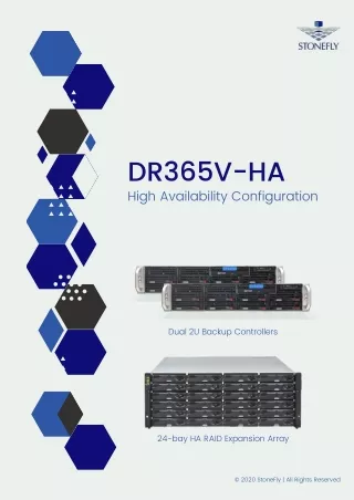
DR365V-HA High Availability Configuration Dual 2U Backup Controllers 24-bay HA RAID Expansion Array © 2020 StoneFly | All Rights Reserved
Copyright © 2006-2020 StoneFly, Inc. All rights are reserved. No part of this document may be photocopied or reproduced without the prior written consent of StoneFly. The information contained in this document is subject to change without notice. StoneFly shall not be liable for errors contained herein or for consequential damages in connection with the furnishing, performance, or use of this material. StoneFly, the StoneFly logo, Storage Concentrator, Integrated Storage Concentrator, ISC, Modular Storage Concentrator, StoneFly Backup Advantage, StoneFusion, StoneFly Replicator CDP, ValueSAN, Unified Scale Out, USO, Super Scale Out, SSO, Twin Scale Out, TSO, Unified Storage & Server, USS, Unified Deduplicated Storage, UDS, Unified Encrypted Storage, UES, OptiSAN, StoneFly Voyager, DR365, DR365 Fusion, StoneFly Mirroring, Storage Concentrator Virtual Machine, SCVM, Software-Defined Unified Storage, SDUS, and StoneFly Cloud Drive are property of StoneFly, Inc. Other brands and their products are trademarks or registered trademarks of their respective holders.
Table of Contents DR365V-HA Setup Guide 1 Table of Contents 1Table of Contents .............................................................................................. 3 Introduction ................................................................................................................................... 5 1.1.1 Icons ....................................................................................................................................... 7 1.1.2 System diagram and description ............................................................................................ 7 1.1.3 Product Registration .............................................................................................................. 8 1.1.4 Contacting StoneFly for Help ................................................................................................ 8 2.1 Mounting the Equipment ............................................................................................................ 10 2.1.1 2U Storage Concentrator Rack Installation Instructions ..................................................... 10 2.1.2 HA RAID Storage Expansion Array / HA Expansion Unit Rack Installation Instructions 10 2.2 Safety Reminders ..................................................................................................................... 22 3.1 Cabling the Equipment ...................................................................................................................... 24 4.1 HA RAID Storage Expansion Array IP Address Configuration ...................................................... 29 4.1.1 Serial port setup ................................................................................................................... 30 4.1.2 Web GUI IP Address setup .................................................................................................. 34 4.2 Configuring IPMI KVM.................................................................................................................. 37 4.3 VMware Management Network Configuration ........................................................................... 43 4.4 Steps to Configure SCVM Management Port (VMware) ............................................................. 50 4.5 Hyper-V Management Network Configuration ........................................................................... 54 4.6 Steps to Configure SCVM Management Port (Hyper-V) .............................................................. 58 4.7 Configuring the SCVM .................................................................................................................. 62 4.8 Configuring the Veeam Management VM ................................................................................... 69 4.8.1 Assigning a Static IP Address to the Veeam Management VM .......................................... 69 4.8.2 Enabling RDP on the Veeam Management VM .................................................................. 73 4.8.3 Accessing Windows Server hosting Veeam ........................................................................ 75 © StoneFly Inc. | All rights reserved Page 3 V8.0.3x
Introduction DR365V-HA Setup Guide Introduction This document is aimed for system administrators who would like to know how to get started with StoneFly DR365V-HA Appliance. It describes initial steps for launching the appliance. The StoneFly DR365-HA combines high availability with backup and disaster recovery to ensure hyper-availability for enterprise mission-critical workloads. Leverage StoneFly’s battle-tested technology and consolidate all of your server and backup systems into one easy to manage, simple-to-use and highly available appliance. This guide gives an overview of the product, rack mounting instructions and initial installation procedure. Information for using the features of the StoneFusion software is found in the Storage Concentrator User Guide on the included CD. StoneFly Resource Library: https://stonefly.com/resources The StoneFly SCVM™ Webpage: https://stonefly.com/hyper-converged/scvm-virtual-storage-appliance Veeam Backup & Replication User Guide for VMware: https://helpcenter.veeam.com/docs/backup/vsphere/overview.html?ver=95u4 Veeam Backup & Replication User Guide for Hyper-V: https://helpcenter.veeam.com/docs/backup/hyperv/overview.html?ver=95u4 Each StoneFly DR365V-HA comes preconfigured with VMware vSphere or Microsoft Hyper-V hypervisor on each cluster node, a StoneFly SCVM™ Virtual Storage Controller on each cluster node, and Veeam’s Backup and Replication Software running on a second VM. Additional Virtual Machines can be installed on the DR365V-HA as needed as long as adequate processing cores and system memory are available to support those VMs. Contact your StoneFly sales representative for details. StoneFly DR365V-HA is made of three or more parts: Two Hyperconverged StoneFly Storage Concentrator (SC) appliances and one or more StoneFly HA RAID Storage Expansion Arrays. StoneFly DR365V-HA supports the following SC cluster appliances: •Dual 1U Storage Concentrator Cluster, Quad 12Gb SAS Connection •Dual 2U Storage Concentrator Cluster, Quad 12Gb SAS Connection •Dual 1U Storage Concentrator Cluster, Quad 16Gb FC Connection •Dual 2U Storage Concentrator Cluster, Quad 16Gb FC Connection © StoneFly Inc. | All rights reserved Page 5 V8.0.3x
Introduction DR365V-HA Setup Guide DR365V-HA 2U Storage Concentrator (with bezel) The StoneFly DR365V-HA can be configured with the following StoneFly HA RAID Storage Expansion Arrays: •12-bay / 2U 12Gb SAS HA RAID Storage Expansion Array (12 x 3.5” SAS drives) •16-bay / 3U 12Gb SAS HA RAID Storage Expansion Array (16 x 3.5” SAS drives) •24-bay / 4U 12Gb SAS HA RAID Storage Expansion Array (24 x 3.5” SAS drives) •24-bay / 2U 12Gb SAS HA RAID Storage Expansion Array (24 x 2.5” SAS drives) •12-bay / 2U 16Gb FC HA RAID Storage Expansion Array (12 x 3.5” SAS drives) •16-bay / 3U 16Gb FC HA RAID Storage Expansion Array (16 x 3.5” SAS drives) •24-bay / 4U 16Gb FC HA RAID Storage Expansion Array (24 x 3.5” SAS drives) •24-bay / 2U 16Gb FC HA RAID Storage Expansion Array (24 x 2.5” SAS drives) StoneFly HA RAID Storage Expansion Arrays can be connected to the following StoneFly HA Expansion Units: •12-bay / 2U 12Gb SAS HA Expansion Unit (12 x 3.5” SAS drives) •16-bay / 3U 12Gb SAS HA Expansion Unit (16 x 3.5” SAS drives) •24-bay / 2U 12Gb SAS HA Expansion Unit (24 x 2.5” SAS drives) •60-bay / 4U 12Gb SAS HA Expansion Unit (60 x 3.5” SAS drives – one drawer) •60-bay / 4U 12Gb SAS HA Expansion Unit (60 x 3.5” SAS drives – two drawers) 24-bay / 4U 12Gb SAS HA RAID Storage Expansion Array V8.0.3x © StoneFly Inc. | All rights reserved Page 6
Introduction DR365V-HA Setup Guide 1.1.1Icons Icon Type Description Note Special instructions or information Warning Risk of system damage or a loss of data 1.1.2System diagram and description The figure below is a network interconnection diagram for the StoneFly DR365V-HA appliance. It consists of two StoneFly hyperconverged Storage Concentrator (SC) cluster nodes. The diagram also includes shared a StoneFly HA RAID Storage Expansion Array with dual active- active hardware RAID controllers with failover and failback. StoneFly DR365V-HA Network Interconnection V8.0.3x © StoneFly Inc. | All rights reserved Page 7
Introduction DR365V-HA Setup Guide 1.1.3Product Registration To initiate StoneFly customer service for your product, you must first register the appliance. Send us an email with the following information: Model Number: ______________ ____________________ Serial Numbers: Your appliance serial numbers start with D500 and are located on the rear of each chassis. 1.1.4Contacting StoneFly for Help Please have the following information available when contacting StoneFly technical support for assistance: Model Number: _____________________ ___________________________ Serial Number(s): D500 _ _ _ _ Software Version: ____________________ __________________________ Initiators: ___________________ ____________________ Storage: ___________________ _____________________ To contact StoneFly call 510.265.1616 (Select support from the menu). Our technical support is available 24 hours a day and 7 days a week. You can also contact us via email at support@stonefly.com V8.0.3x © StoneFly Inc. | All rights reserved Page 8
2.1Mounting the Equipment The DR365V-HA appliance is comprised of at least two StoneFly hyperconverged SCs and one HA RAID Storage Expansion Array. Depending on which model you purchased, the interconnects between the SCs and the HA RAID Storage Expansion Array will be either SAS or FC. The SAS cables connecting the SCs with the HA RAID Storage Expansion Arrays and optional HA Expansion Units are short. When mounting the units, you should make sure that the units are rack mounted close to each other. The following installation process describes how you can mount two 1U SC appliances and a standard 2U HA RAID Storage Expansion Array. To ensure proper installation and functionality of the StoneFly appliance, please observe the following warnings: •Wear an anti-static wristband before and during the installation procedure. •It is recommended to plug the system into two different power sources (eg. into a power outlet and another into a UPS). •Ensure the rack which the enclosure will be mounted onto has proper grounding and over-current protection. •Do not obstruct ventilation openings; provide 20cm of free space at the front and back of the enclosure for air circulation; keep the ambient temperature below 35 degrees Celsius. 2.1.1 2U Storage Concentrator Rack Installation Instructions This section provides information on installing the 2U Hyperconverged Storage Concentrator appliance(s) into a rack or cabinet with the rails provided. There are a variety of rack/cabinet units on the market, which may mean that the assembly procedure will differ slightly. You should also refer to the installation instructions that came with the rack unit you are using. NOTE: This rail will fit a rack/cabinet between 26" and 33.5" deep. Identifying the Sections of the Rack Rails The StoneFly appliance chassis package includes two rack rail assemblies in the rack mounting kit. Each assembly consists of three sections: an inner rail that secures directly to the chassis, an outer rail that secures to the rack, and a middle rail which extends from the outer rail. These assemblies are specifically designed for the left and right side of the chassis.
Identifying the Outer Rail, Middle Rail and Inner Rail (Left Rail Assembly Shown)
Releasing the Inner Rail Each inner rail has a locking latch. This latch prevents the server from coming completely out of the rack when the chassis is pulled out for servicing. To mount the rail onto the chassis, first release the inner rail from the outer rails. Releasing the Inner Rail from the Outer Rails: 1.Pull the inner rail out of the outer rail until it is fully extended as illustrated below. 2.Press the locking tab down to release the inner rail. 3.Pull the inner rail all the way out. 4.Repeat for the other outer rail. Extending and Releasing the Inner Rail
Installing the Inner Rails on the Chassis Installing the Inner Rails 1.Identify the left and right inner rails. They are labeled. 2.Place the inner rail firmly against the side of the chassis, aligning the hooks on the side of the chassis with the holes in the inner rail. 3.Slide the inner rail forward toward the front of the chassis until the quick release bracket snaps into place, securing the rail to the chassis. 4.Optionally, you can further secure the inner rail to the chassis with a screw. 5.Repeat for the other inner rail. Installing the Inner Rails Inner Rails Installed on the Chassis
Installing the Outer Rails onto the Rack Installing the Outer Rails 1.Press upward on the locking tab at the rear end of the middle rail. 2.Push the middle rail back into the outer rail. 3.Hang the hooks on the front of the outer rail onto the square holes on the front of the rack. If desired, use screws to secure the outer rails to the rack. 4.Pull out the rear of the outer rail, adjusting the length until it just fits within the posts of the rack. 5.Hang the hooks of the rear section of the outer rail onto the square holes on the rear of the rack. Take care that the proper holes are used so the rails are level. If desired, use screws to secure the rear of the outer rail to the rear of the rack. Extending and Mounting the Outer Rails The rack stabilizing mechanism must be in place, or the rack must be bolted to the floor before you slide the unit out for servicing. Failure to stabilize the rack can cause the rack to tip over. Do not use a two post “telco” type rack.
Initial Introduction DR365V-HA Setup Guide Sliding the Chassis onto the Rack Rails Warning: Mounting the system into the rack requires at least two people to support the chassis during installation. Please follow the safety recommendations printed on the rails. Installing the Chassis into a Rack 1.Extend the outer rails as illustrated above. 2.Align the inner rails of the chassis with the outer rails on the rack. 3.Slide the inner rails into the outer rails, keeping the pressure even on both sides. When the chassis has been pushed completely into the rack, it should click into the locked position. 4.Optional screws may be used to hold the front of the chassis to the rack. Installing the Chassis into a Rack Note: The figure above is for illustrative purposes only. Always install servers to the bottom of the rack first. Caution: Do not pick up the server with the front handles. They are designed to pull the system from a rack only. V8.0.3x © StoneFly Inc. | All rights reserved Page 15
Initial Introduction DR365V-HA Setup Guide 2.1.2 HA RAID Storage Expansion Array / HA Expansion Unit Rack Installation Instructions Rack Ear Mount Kit The following table shows all accessories that came with the rack ear mount kit. V8.0.3x © StoneFly Inc. | All rights reserved Page 16
Initial Introduction DR365V-HA Setup Guide Installation Procedure The installation begins with determining the installation position and M5 cage nut (9) insertion locations. Install the fixed rack ear mount to the rear posts and secure them using truss head screws (4). V8.0.3x © StoneFly Inc. | All rights reserved Page 17
Initial Introduction DR365V-HA Setup Guide With the assistance of another person holding the enclosure at the installation height, the other person can place four M5 x 25mm (6) at the front of the enclosure and eight #6-32 screws (3), four on each side, to secure the enclosure into the rack. V8.0.3x © StoneFly Inc. | All rights reserved Page 18
Initial Introduction DR365V-HA Setup Guide Slide Rail Kit The following table shows all accessories that came with the slide rail kit. V8.0.3x © StoneFly Inc. | All rights reserved Page 19
Initial Introduction DR365V-HA Setup Guide The installation begins with determining the installation position (front and rear rack positions) and M5 cage nut (5) insertion location. V8.0.3x © StoneFly Inc. | All rights reserved Page 20
Initial Introduction DR365V-HA Setup Guide Adjust the length by loosening the four screws on the slide rail. Secure the slide rails to front and rear posts using truss head screws. Tighten the four screws on the slide to fix the length. Attach the inner glides to BOTH sides of the enclosure using flathead screws #6-32 (8). With the assistance of another person, lift and insert the enclosure onto the slide rail. Make sure the inner glides on both sides of the enclosure meets the inner glide rail. Secure the enclosure with M5 or M6 screws from the front. V8.0.3x © StoneFly Inc. | All rights reserved Page 21
Initial Introduction DR365V-HA Setup Guide 2.2 Safety Reminders If you must relocate the enclosure after installation •Cease all input / output transactions, shut down the system, disconnect all the cables (please refer to the User Manual for details). •Empty all drive bays (hard drives + hard drive trays) and transport them separately in safe packaging. •Modules came installed within the enclosure need not be removed. •Follow the instructions provided in the StoneFly Getting Started Guide. When the system is in operation •Module and drive bays must not be empty! They must have a dummy cover / plate in place to stabilized internal airflow! •Should a module fail, leave it in its place until you have the replacement item on-hand to take its place. •Allow at least 18~20cm of clearance space at the rear of the enclosure for ventilation. •Avoid touching the PCB and gold-finger connections. V8.0.3x © StoneFly Inc. | All rights reserved Page 22
Cabling Connections & Power Up DR365V-HA Setup Guide 3.1 Cabling the Equipment The following description shows the steps for two Storage Concentrators, and one HA RAID Storage Expansion Array. Please make sure that you’ve securely mounted the appliances in the rack/cabinet before beginning the cabling. It’s also important to note that the power is connected AFTER all of the data/network connections have been made. Spanning Tree Protocol (STP) must be disabled on your network switch when using bonded data ports on the StoneFly DR365V-HA appliance. Note: Follow the labels for each port as marked on your appliance(s). SAS Interconnects – Standard Configuration Connect the two included Mini-SAS HD cables between each SC and the HA RAID Storage Expansion Array, as shown below: V8.0.3x © StoneFly Inc. | All rights reserved Page 24
Cabling Connections & Power Up DR365V-HA Setup Guide SAS Interconnects - Multipath Connections (Optional Upgrade) If you have purchased the optional StoneFly Multipathing Kit, then you will be able to connect each SC to both RAID controllers on the HA RAID Storage Expansion Array. The four Mini-SAS HD cables will be connected between each SC and the HA RAID Storage Expansion Array, as shown below (optional multipathing configuration): V8.0.3x © StoneFly Inc. | All rights reserved Page 25
Cabling Connections & Power Up DR365V-HA Setup Guide Network Connections Connect SFP+ cables to the data ports on each SC, and Ethernet cables to each of the Management ports (MGMT) on all three units as shown below. For best practices, split the connections between at least two switches for each type of port. V8.0.3x © StoneFly Inc. | All rights reserved Page 26
Cabling Connections & Power Up DR365V-HA Setup Guide Power Connections Note: Make sure to make all the connections for both SCs as described above before connecting the power cords to the system. Once you’ve made all the connections and made sure that there are no loose cords, press the power button to turn on the system. V8.0.3x © StoneFly Inc. | All rights reserved Page 27
Software Configuration DR365V-HA Setup Guide 4.1HA RAID Storage Expansion Array IP Address Configuration You can configure the IP address for the HA RAID Storage Expansion Array via either the Serial port or Ethernet port on the rear of the unit. Serial port: A Y-cable is provided in the package. (NOTE: null modem may be required if you are using a third-party cable). The serial port’s defaults are: Baud Rate 38400 Data Bit 8 Parity None Stop Bit 1 Flow Control Hardware For TCP/IP connection and firewall configuration with a management station running the storage array’s web interface, please refer to storage array web interface online help or User’s Manual. If your network environment is not running DHCP server protocols, a default IP address of <10.10.1.1> can be used to access the unit for the first time. Use the Ethernet management port for management purposes only, i.e., storage array web interface or telnet console. This Ethernet management port is not used for I/O transactions. Management network ports are boxed in red, serial ports are boxed in blue. This is an example controller, controllers do vary from configuration to configuration. V8.0.3x © StoneFly Inc. | All rights reserved Page 29
Software Configuration DR365V-HA Setup Guide 4.1.1 Serial port setup When setting up via the serial port, enter the settings as shown below: V8.0.3x © StoneFly Inc. | All rights reserved Page 30
Software Configuration DR365V-HA Setup Guide Hit ESC to view next screen. Select PC Graphic (ANSI Mode) then hit enter. V8.0.3x © StoneFly Inc. | All rights reserved Page 31
Software Configuration DR365V-HA Setup Guide Select view and edit Configuration parameters then hit enter. Select Communication Parameters and hit enter. V8.0.3x © StoneFly Inc. | All rights reserved Page 32
Software Configuration DR365V-HA Setup Guide Select Internet Protocol (TCP/IP) and hit enter. Select lan0 and hit enter, then select static and enter the IP address as needed. V8.0.3x © StoneFly Inc. | All rights reserved Page 33
Software Configuration DR365V-HA Setup Guide 4.1.2 Web GUI IP Address setup When setting up via the Ethernet port/web GUI, follow the instructions as shown below: The default Password is blank. Just click on the Login button. Click on System Settings. V8.0.3x © StoneFly Inc. | All rights reserved Page 34
Software Configuration DR365V-HA Setup Guide Select Communication. Select Management Port then click on the Configure button. V8.0.3x © StoneFly Inc. | All rights reserved Page 35
Software Configuration DR365V-HA Setup Guide Select Static then enter your network information. Click OK when completed. V8.0.3x © StoneFly Inc. | All rights reserved Page 36
Software Configuration DR365V-HA Setup Guide 4.2Configuring IPMI KVM The Intelligent Platform Management Interface (IPMI) KVM configuration allows for Remote Management and Power Control of the StoneFly DR365V-HA system. This configuration is optional to perform, but recommended. To configure the IPMI module, connect a keyboard and monitor to the system. Power on the system and press the Del key to enter the BIOS setup. Navigate to IPMI tab and go to BMC Network Configurations: V8.0.3x © StoneFly Inc. | All rights reserved Page 37
Software Configuration DR365V-HA Setup Guide In the BMC Network Configuration tab, select Update IPMI LAN Configuration and press Enter: When prompted, select Yes and press Enter. From the additional list of options, select Configuration Address Source and press Enter: V8.0.3x © StoneFly Inc. | All rights reserved Page 38
Software Configuration DR365V-HA Setup Guide From the prompt, select Static and press Enter: Enter the Static IP Address, Subnet Mask and Gateway IP Address. V8.0.3x © StoneFly Inc. | All rights reserved Page 39
Software Configuration DR365V-HA Setup Guide When entering addresses, please note: 1.IP Address 2.IP Subnet Mask 3.Default Gateway Press the “ESC” key to exit. Navigate to the Exit tab and select Save Changes and Exit. Note: The system will require power to be removed before IPMI IP Address will take effect. Accessing the IPMI Interface Start a browser and navigate to the configured IP address. Must be on the same subnet as DR365V’s Management port Same as DR365V-HA’s Management port Same as DR365V-HA’s Management port V8.0.3x © StoneFly Inc. | All rights reserved Page 40
Software Configuration DR365V-HA Setup Guide Enter the following information in the login screen: •Username: stonefly •Password: Stonefly1 Navigate to Remote Control tab and select iKVM/HTML5: V8.0.3x © StoneFly Inc. | All rights reserved Page 41
Software Configuration DR365V-HA Setup Guide Click on iKVM/HTML5 to launch remote console: V8.0.3x © StoneFly Inc. | All rights reserved Page 42
Software Configuration DR365V-HA Setup Guide 4.3VMware Management Network Configuration This section describes configuration of the ESXi Management Network. IP Addresses and Hostnames used in this section are for example only. Refer to section 4.5 for Hyper-V Management Network Configuration. Connect to System console. Attach a keyboard and monitor or use system IPMI KVM. Press the “F2” key to customize system. Then enter Login Name and Password and hit the “Enter” key to continue. The default Login information is as follows: •Log in Name: root •Password: Stonefly1! V8.0.3x © StoneFly Inc. | All rights reserved Page 43
Software Configuration DR365V-HA Setup Guide Select Network Adaptersand press the “Enter” key. Select the vmnicto use for the management network for ESXi and press the “Enter” key. Press the “Esc” key when changes are complete. V8.0.3x © StoneFly Inc. | All rights reserved Page 44
Software Configuration DR365V-HA Setup Guide Select IPv4 Configuration, then hit the “Enter” key. Select Set static IPV4 address and network configuration. Enter the IP Addresses as needed, then hit the “Esc” key to return. V8.0.3x © StoneFly Inc. | All rights reserved Page 45
Software Configuration DR365V-HA Setup Guide Select IPv6 Configuration, then hit the “Enter” key. On the following screen, select Disable IPv6 (restart required),then press the “Esc” key. V8.0.3x © StoneFly Inc. | All rights reserved Page 46
Software Configuration DR365V-HA Setup Guide Select DNS Configuration, then press the “Enter” key. Enter information for DNS server and Hostname as needed then hit the “ESC” key to return. V8.0.3x © StoneFly Inc. | All rights reserved Page 47
Software Configuration DR365V-HA Setup Guide Select Custom DNS Suffixes, then hit the ESC key to return. Enter DNS Suffixes as needed, then hit the ESC key to return. V8.0.3x © StoneFly Inc. | All rights reserved Page 48
Software Configuration DR365V-HA Setup Guide Select Restart Management Networkto complete configuration of settings. Hit the “ESC” key to log out. V8.0.3x © StoneFly Inc. | All rights reserved Page 49