Download
1 / 23
260 likes | 588 Views
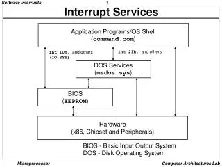
Interrupt Controller. Introduction to 8259. Poll Method. Interrupt Method. Features of 8259. 8086, 8088 Compatible MCS-80 , MCS-85 Compatible Eight-Level Priority Controller Expandable to 64 Levels Programmable Interrupt Modes Individual Request Mask Capability

E N D
Interrupt Controller Introduction to 8259
Features of 8259 8086, 8088 Compatible MCS-80, MCS-85 Compatible Eight-Level Priority Controller Expandable to 64 Levels Programmable Interrupt Modes Individual Request Mask Capability NMOS Tech. and Single +5V Supply (No Clocks) Available in 28-Pin DIP and 28-Lead PLCC Package Available in EXPRESS Standard Temperature Range Extended Temperature Range
Packaging Pins: D0-D7 RD_ WR_ CS_ A0 INTA_ IR0 – IR7 INT SP_/CN_ CAS0 – CAS2 Vcc GND
Interrupt Sequences • One or more of the INTERRUPT REQUEST lines (IR7±0) are raised high, setting the corresponding IRR bit(s). • The 8259A evaluates these requests, and sends an INT to the CPU, if appropriate. • The CPU acknowledges the INT and responds with an INTA pulse. • Upon receiving an INTA from the CPU group, the highest priority ISR bit is set and the corresponding IRR bit is reset. The 8259A does not drive the Data Bus during this cycle. • The 8086 will initiate a second INTA pulse. During this pulse, the 8259A releases an 8-bit pointer onto the Data Bus where it is read by the CPU. • This completes the interrupt cycle. In the AEOI mode the ISR bit is reset at the end of the second INTA pulse. Otherwise, the ISR bit remains set until an appropriate EOI command is issued at the end of the interrupt subroutine.
PROGRAMMING THE 8259A The 8259A accepts two types of command words generated by the CPU: • Initialization Command Words (ICWs): Before normal operation can begin, each 8259A in the system must be brought to a starting point by a sequence of 2 to 4 bytes timed by WR pulses. • Operation Command Words (OCWs): These are the command words which command the 8259A to operate in various interrupt modes. These modes are: • Fully nested mode • Rotating priority mode • Special mask mode • Polled mode The OCWs can be written into the 8259A anytime after initialization.
Reset State Whenever a command is issued with A0 = 0 and D4 = 1, this is interpreted as Initialization Command Word 1 (ICW1). ICW1 starts the initialization sequence during which the following automatically occur. • The edge sense circuit is reset, which means that following initialization, an interrupt request (IR) input must make a low-to-high transition to generate an interrupt. • The Interrupt Mask Register is cleared. • IR7 input is assigned priority 7. • The slave mode address is set to 7. • Special Mask Mode is cleared and Status Read is set to IRR. • If IC4 = 0, then all functions selected in ICW4 are set to zero. (Non-Buffered mode*, no Auto- EOI, MCS-80, 85 system).
ICW3 Master Mode Slave Mode
Data Storage Policy Transmit TX_Service TX_FIFO Process PPI RX_FIFO RX_Service Receive
Initializing PPI • INIT_PPI: • MOV AL , 40H ;01XXXXXX Selecting Mode 2 • OUT PPICOM , AL • MOV AL,1 • MOV [TX_FLAG] , AL ; Flag Indicating Empty Buffer • XOR AL , AL • MOV [RX_FLAG] , AL ; Flag Indicating Empty Buffer • MOV [TX_head],AL • MOV [RX_head],AL • MOV [TX_tail],AL • MOV [RX_tail],AL • RET
Checking FIFO • TX_AVAIL_SIZE: • MOV AL,[TX_head] • MOV BL,[TX_tail] • SUB AL,BL • RET • TX_EMPTY_SIZE: • MOV AL,[TX_head] • MOV BL,[TX_tail] • SUB AL,BL • NOT AL • RET • RX_AVAIL_SIZE: • MOV AL,[RX_head] • MOV BL,[RX_tail] • SUB AL,BL • RET • RX_EMPTY_SIZE: • MOV AL,[RX_head] • MOV BL,[RX_tail] • SUB AL,BL • NOT AL • RET