Download

1 / 34
340 likes | 632 Views
First look at collimation in cold regions (around IR's). R.W. Assmann, G. Bellodi , R. Bruce, J. Jowet , L. Lari , S. Redaelli , A. Rossi, T. Weiler , D. Wollmann 1 st HiLumi / LARP collaboration meeting 17 November 2011. Outline. The LHC collimation system Collimation efficiency

E N D
First look at collimation in cold regions (around IR's) R.W. Assmann, G. Bellodi, R. Bruce, J. Jowet, L. Lari, S. Redaelli, A. Rossi, T. Weiler, D. Wollmann 1stHiLumi / LARP collaboration meeting 17 November 2011
Outline Preliminary Meeting on Interface 11 T - Cold Collimation, 05.10.11 The LHC collimation system Collimation efficiency Leaks in DS regions for protons and ions Interim conclusions Origin of losses Improving collimation efficiency Studies made so far Summary and conclusions
Layout of LHC collimation system Two warm cleaning insertions, 3 collimation planes IR3: Momentum cleaning per beam 1 primary (H) 4 secondary (H) 4 shower abs. (H,V) IR7: Betatron cleaning per beam 3 primary (H,V,S) 11 secondary (H,V,S) 5 shower abs. (H,V) Local cleaning at triplets8 tertiary (2 per IP) per beam Momentum cleaning Betatron cleaning Passive absorbers for warm magnets Physics debris absorbers Transfer lines (13 collimators)Injection and dump protection (10) Total of 108 collimators (100 movable). Two jaws (4 motors) per collimator! Picture by C. Bracco
Collimation for beam cleaning and machine protection Betatron cleaning insertion • Three-stage cleaning system for the protection of the arc cold aperture at injection. • At collision machine bottleneck at superconducting triplets. Tertiary collimators closed (four-stage cleaning system). Courtesy of C. Bracco for injection and collision (7TeV) Horizontal (TCTH) and vertical (TCTV) tertiary collimators are installed upstream of the triplet magnets to provide protection during squeeze and collision. The halo leakage to cold aperture must be below quench limit!
Collimation for beam cleaning and machine protection R. Bruce IPAC’11 Betatron cleaning insertion β* 3.5m β* 1m β* 0.55m Primary and secondary collimators are robust (Carbon-based). For HiLumi secondary collimator in metal-diamond (higher absorption, lower impedance). Absorbers and tertiary collimators (Tungsten) are not and must be protected.
The Phase I Collimator 1.2 m Tunnel installation (TCT in IP2) 360 MJ proton beam 3 mm beam passage at top energy, with RF contacts for guiding image currents 1.4m total length, flange to flange Water cooling system (capacity for 420kW in IR7 and 160kW in IR3).
Typical geometry (here hor TCT) W Jaws Watercooling pipes Maximum energy deposition for W plastic deformation (one shot) 480 J/cm3≈ 1E9 p+ (5TeV*) *Extrapolated from V. Kain’s talk at Chamonix 2009, for a squeezed beam Joint LBS & LPC meeting
Collimation measured performance • Local cleaning efficiency • Ntotal = Total no. of particles leaving the cleaning insertion with a normalised amplitude > A in Ds • Nabs = Total no. of particles undergoing inelastic interactions and being absorbed at collimators 2010-2011 Efficiency at Q8 downstream IR7 at 3.5TeV, B1 and B2 Measured with loss maps (losses at BLM when blowing the beam) 10-3 99.960 % 10-4 99.995 %
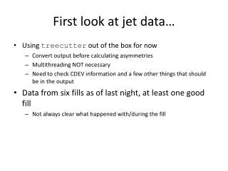
Losses during physics, 1308b nom. at 3.5TeV • Losses in DS of experimental Regions could become limiting -clean. intensity IR5 lumi mom-clean. intensity IR8 lumi IR1 lumi dumpprotection IR2 lumi
Losses during physics, 1308b nom. at 3.5TeV Zoom in IR7: betatron losses -clean.
Losses during physics, 1308b nom. at 3.5TeV - Does not include significant loads from ion operation. - Does not include effect of b* Zoom in IR5: luminosity losses TAN TAN TAS | | MBWX MBWX
Global view of losses, Pb-Pb stable beams Record luminosity, the last fill of 2010 Momentum collimation: 208Pb82+ (IBS) 207Pb82+ (EMD1) Betatron collimation: 206Pb82+ (EMD2 in TCP) + many other nuclides from hadronic fragmentation and EMD in TCPs 208Pb81+(BFPP at ATLAS) 208Pb81+ BFPP at CMS 208Pb81+(BFPP at ALICE) Possibly: 206Pb82+ (EMD2 at IPs), other nuclides from collimation ?? J.M. Jowett, Chamonix 2011 G. Belodi - LHC Collimation Review 2011
Interim conclusions • The present collimation system works very well. Reached 99.995% collimation efficiency with 50% smaller gaps than design. • It is predicted to work for proton nominal intensity (Collimation review June 2011), and for ions? • HL-LHC requires catching losses in the DS regions. Even if such losses do not quench the magnets, they may cause damage if permanently close to quench limit. • DS collimators are needed in 5 Interaction Regions for: • IR1 and IR5 for proton luminosity • IR2/1/5 for ion luminosity • IR3/7 for proton and ion intensity • Priority: DS1 – 2 – 5 then 3 – 7 then 8
Origin of Losses in Dispersion Suppressor Collimator Warm cleaning insertion (straight line) SC bend dipole (acts as spectrometer) SC quad for p, and dipoles for ions (hit by halo) Off-momentum particles generated by particle-matter interaction in collimators and by collision at IPs (proton single diffractive scattering, and ion dissociation/fragmentation) pass thorough LSS Ideal orbit (on momentum) Already predicted in 2003
Improving Collimation Efficiency Add collimator, using space left by missing dipole Collimator Warm cleaning insertion (straight line) SC bend dipole (acts as spectrometer) SC quad Ideal orbit (on momentum) Reduce number of off-momentum protons produced (phase 2 primary and secondary collimators, with higher absorbtion). Does not work for ions. Install collimators into SC area, just before loss locations to catch off-momentum particles before they get lost in SC magnets.
Q7 Q8 Q9 Q10 Q11 MB MB MB MB MB MB MB MB Example 1 studied: protons TCRYOA TCRYOB Beam 1 Collimation Upgrade Review 2011 • DS3-7 collimators (present solution at RT) • Tungsten collimators in front of Q8 and Q10 to catch off momentum particles (from Single Diffractive scattering at collimators, from collisions …) at high dispersion regions. • Layout and optics checked with MADX. No problem for the optics and survey seen. Optics change (move of Q7) small even without optics rematch. • Space assumed for two 2-sided (for ions), 1mx(20x34)mm W jaw insert, with tapering (10cm per side), RF fingers, cooled for 500W (ions)
IR3 Dispersion Suppressor Collimator Beam vacuum sector valves Standard interconnects Manual quick connect flanges, electrical and water plugs, but not remote handling Collimator Bypass cryostat BLM’s “Standard” baked vacuum sector Collimator with independent support/alignment Collimator replacement without re-alignment A. Dallocchio
Zoom into DS downstream of IR7 quench level T. Weiler Impact pattern of protons on DS collimator 1 Impact pattern of protons on DS collimator 2 R. Assmann - HHH 2008
Example 2 studied: IR2 solutions for ions Optimal position for one “DS-collimator/beam. Collimators in dispersion suppressors around experiment(s) will be needed to overcome luminosity (not intensity) limit for Pb-Pb collisions.
Summary and conclusions Preliminary Meeting on Interface 11 T - Cold Collimation, 05.10.11 • The present collimation system works very well. Reached 99.995% collimation efficiency with 50% smaller gaps than design. • Present system is predicted to work for nominal LHC proton intensity, but for ions? • BUT there are still losses in the DS regions due to off-momentum particles that go through the LSS and are caught at SC magnets. This is a basic limitation coming from physics processes. • DS collimators (1m active tungsten jaw) have been shown to solve this limit (factor of 15 improvement in cleaning efficiency, also confirmed by FLUKA) • HL-LHC needs DS collimators in 5 Interaction Regions for: • IR1 and IR5 for proton luminosity • IR2/1/5 for ion luminosity • IR3/7 for proton and ion intensity • Priority: DS1 – 2 – 5 then 3 – 7 then 8
Betatron losses fully confirmed B1 Simulations: perfect machine, B1 vertical, 3.5TeV, IR7superimposed on Betatron loss maps Intermediate settings Q7 Q8 Q10 Q9 Q11 Tight Settings When will they quench ? 99.995% efficiency with tight settings Q7 Q8 Q10 Q9 Q11 Preliminary Meeting on Interface 11 T - Cold Collimation, 05.10.11 A. Rossi
Ions: Beam 2 Leakage from IR7 Collimation (much worse than for protons, as expected) Level simulated
Ion commissioning loss maps vs simulation – Nov 2010 B1H G. Bellodi - LHC Collimation Review 2011
DS collimator designed for IR3 Collimator Module Cryo-bypass A. Dallocchio
Simulation results for IR3 combined cleaning, vertical B1 BLM thresholdafter MD Cleaning inefficiency withoutDS collimator. Simulation for ideal machine, 7TeV, vertical Preliminary Meeting on Interface 11 T - Cold Collimation, 05.10.11
Simulation results for IR3 combined cleaning, vertical B1 Cleaning inefficiency withoutDS collimator. Simulation for ideal machine, 7TeV, vertical Preliminary Meeting on Interface 11 T - Cold Collimation, 05.10.11
Cleaning inefficiency with DS collimators IR3 combined cleaning for ideal machine with DS collimator at 15 s, 7TeV, vertical B1 Preliminary Meeting on Interface 11 T - Cold Collimation, 05.10.11
Cleaning inefficiency with DS collimators Zoom in IR3 B1 Calculations including alignment imperfections show a worsening in the vertical plane only by max. a factor of ~ 7.5 (average 4.5) Preliminary Meeting on Interface 11 T - Cold Collimation, 05.10.11
Cleaning inefficiency with machine alignment imperfections RMS offsets (measured) in the horizontal and vertical planes defined for families of elements. DS collimator at 15 s. 7TeV, vertical sheet beam 1, Studies with aperture imperfections Performance worsen by max. a factor of ~ 7.5 (average 4.5) in the vertical plane, ~ 2 (average 0.7) in the horizontal plane (over 10 cases studied)
IR3 combined cleaning for ions Without TCRYO t=12 min lifetime 7×107 ×592= 4.14×10¹⁰ ions E=7 Z TeV eq. Max TCP load ~ 4500W Peak loss in DS3 ~ 20W/m h (local) = 0.0044 With TCRYO G. Bellodi - LHC Collimation Review 2011
Fill 2156: proton beam - physics Ramp and collision Loss maps Increase due to increasing lumi in IP1 Tune trim of +0.001 on beam2 H Preliminary Meeting on Interface 11 T - Cold Collimation, 05.10.11
p – C Interaction: Multiple Coulomb &Single-Diffractive Scattering
Monte-Carlo Simulation of Realistic Beam Halo and Interactions