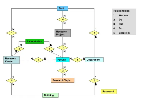
3D LED Matrix Cube User Manager: Construction and Control of Interactive Display
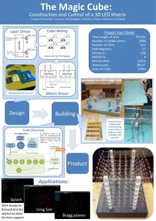
This project involves the design and implementation of a 3D LED matrix display controlled via a user manager application developed for PC. The display features 512 LEDs organized into a cube and operates using a multiplexing circuit connected to a microcontroller. It includes a user-friendly interface built in Java, utilizing Processing libraries and OpenGL for rendering. Total wiring length is 79.12m, with 2096 solder joints and a refresh rate of 122Hz. The project emphasizes educational applications, including simulations like IsingSim and Bragg planes.

3D LED Matrix Cube User Manager: Construction and Control of Interactive Display
E N D
Presentation Transcript
The Magic Cube: PC Application User Manager Construction and Control of a 3D LED Matrix Display Thread Cube User Thread S.Dove, B.Fernandes, T.Loussert, M.Overington, E.Overton, C.Ryan. Supervisor: Dr M.Grell Multiplexing Circuit Shared Cube Serial Thread To Cube Serial Link Microcontroller Layer Driver Display Logic Project Fact Sheet Total Length of wire: 79.12m Number of Solder Joints: 2096 Number of LEDs: 512 Shift Registers: 17 Resistors: 128 MOSFETS: 8 Refresh Rate : 122Hz Dimensions: 28cm3 Lines of Code: 1700+ INIT WAIT BEGINCUBE WAIT BEGINLAYER GET LAYER WAIT END LAYER WAIT END CUBE Layer GND 74HC595N Timer Interrupt To Micro-controller Q0 DIN ERROR Layer GND To Layer CLK TCLK Qn CLK 74HC595N Qn Qn+1 74HC595N Qn Qn+1 DIN TCLK CLK DOUT DIN TCLK CLK Multiplexing test: Success! Data Clock Layer Update To Microcontroller Matrix Driver Data In Design Building Cube Wiring Layer GND Clockwise from bottom left: Partial driving circuit, Cube in progress, Layer template, LED example. Layer GND Positive Drive from Shift Registers Product Code Overview PC application written in Java using the www.processing.org libraries and OpenGL bindings for rendering. Microcontroller Code written in Wiring using the Arduino IDE. Applications: Splash With thanks to Richard And the workshop team for their support IsingSim Bragg planes