Download
1 / 39
400 likes | 634 Views
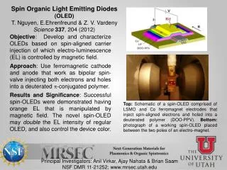
Phys 590B-2009-04-01. Organic Light-Emitting Devices (OLEDs): A Brief Overview Joe Shinar jshinar@iastate.edu. Support, mostly by DOE, gratefully acknowledged Support by NASA, NSF, & NIH also gratefully acknowledged. Current Issues in the Science & Technology of OLEDs:.

E N D
Phys 590B-2009-04-01 Organic Light-Emitting Devices (OLEDs): A Brief Overview Joe Shinar jshinar@iastate.edu Support, mostly by DOE, gratefully acknowledged Support by NASA, NSF, & NIH also gratefully acknowledged
Current Issues in the Science & Technology of OLEDs: • Internal quantum efficiency, at low & high current densities • Outcoupling or extraction efficiency. • Power efficiency, at low & high current densities. • Stability & degradation mechanisms: Oxidation (by water), crystallization, delamination, atomic In, Na, etc. (electro)migration. • Is an organic injection laser (i.e., an organic diode laser) feasible?
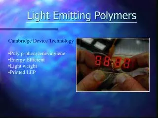
Basic Nature of p-Conjugated Materials A carbon-based (small) molecule or polymer with alternating single (s) and double (s & p) bonds. Examples: poly(p-phenylene) vinylene (PPV) Polyfluorene (PFO) methyl-bridged ladder-type poly(p-phenylene ) (m-LPPP) 4,4'-bis(2,2'-diphenylvinyl)-1,1'-biphenyl (DPVBi) tris(8-hydroxy quinoline) Al (Alq3)
pz Basic Nature of p-Conjugated Materials (cont.) • Consider ethylene (C2H4): • sp2 hybridization: three sp2 orbitals 120o to each other, pz orbital perpendicular to the sp2 plane. • In benzene (C6H6) ring: ψ2 and ψ3 are HOMO – Valence band ψ4*, ψ5* are LUMO – Conduction band
Basic Nature of p-Conjugated Materials (cont.) • PPV: • Electrons in p orbitals have higher energy than those in s orbitals. • The energy gap between • the highest occupied molecular orbital (HOMO) • (analogous to the top of the valence band in inorganic semiconductors) • & the lowest unoccupied molecular orbital (LUMO) • (analogous to the bottom of the conduction band in inorganic semiconductors • is 1.5 – 3.5 eV, i.e., it covers the whole visible range.
Low-Workfunction Cathode + Electron-Transporting & Emitting layer (ETL) Hole-Transporting Layer (HTL) Transparent Conducting Anode [indium tin oxide (ITO)] Glass or Plastic Substrate - Basic structure of some (blue) OLEDs DPVBi : Pe:CBP a-NPD 4,4'-bis(2,2'-diphenylvinyl)-1,1'-biphenyl (DPVBi), Perylene:4,4'-bis(9-carbazolyl)biphenyl (Pe:CBP) N,N’-diphenyl-N,N’-bis(1-naphthyl phenyl)-1,1’-biphenyl-4,4’-diamine (a-NPD)
Basic Operation, forward bias Lowest unoccupied molecular orbital (LUMO) Metal cathode e- Energy e- EF ITO Anode ETL HTL EF h+ Highest occupied molecular orbital (HOMO) Position (from ITO anode bottom to methal cathode top
The state-of-the-art in OLEDs • Numerous red-to-blue small-molecular- and polymer-OLEDs • Fluorescent Green, yellow & red small molecular OLEDs with continuous lifetimes > 300,000 hours (> 12,000 days > 33 yrs), hext ~ 4%, power efficiency ~2%, at brightness of ~150 Cd/m2 • Blue small molecular OLEDs with continuous lifetimes ~100,000 hours (> 4000 days > 12 yrs), hext ~ 3%, power efficiency hP ~ 1.5%. • Electrophosphorescent Red, green, & blue OLEDs, i.e., emission is from Triplet (Excitons), so efficiency can be very high -- hext ~ 18%, 19%, & 7%, hP ~ 9%, 9.5%, 3%, respectively.
Cd/m2 ???? • 1 Cd/m2 = 1 lumen/steradian = 1 lm/str = [1.46 mW @ 555 nm]/str • For Lambertian source, 1 lm/str total of p lm • Typical values: TV or computer monitor, 100 – 300 Cd/m2. 60 W incandescent light bulb, 840 lumens. Power efficiency hP = [840 lm]/[60 W] = 14 lm/W [1.20 W light]/[60 W electrical] = 2% Fluorescent tubes, 40 hP 60 lm/W, i.e., 6 hP 9 %
OLED Efficiencies • Internal quantum efficiency IQEof fluorescent OLEDs hint 0.25 Why? Can it be improved? • Outcoupling or extraction efficiency hout 0.33 Why? Can it be improved? • [Photon energy (in V)]/[Applied Voltage] = Vg / Vappl < 0.50 Why? Can it be improved? Note: 0.250.330.50 ~ 0.04
Internal Quantum Efficiency: Carrier injection into a luminescent p-conjugated molecule or polymer The most basic process in all light-emitting diodes (LEDs): Bottom of conduction band, inorganic semiconductor LUMO, organic semiconductor Electron e- from cathode e- e- h+ & e- meet to form an exciton on a molecule or same conjugated segment of polymer Photon emission h+ h+ Hole h+ from anode HOMO, organic semiconductor Top of valence band, inorganic semiconductor
How many distinct SE & TE quantum states? + TE, Spin 1, Sz = +1 = + TE, Spin 1, Sz = 0 =
How many distinct SE & TE quantum states (cont.)? TE, Spin 1, Sz = -1 + = SE, Spin Sz = 0 + = 0
In summary: • 3 TE states (S = 1): () (Sz = +1), ( + )/2 (Sz = 0), () (Sz = -1). • 1 SE state (S = 0): ( - )/2 (S = 0). • In fluorescent organic materials, only the SE decays radiatively, to yield the photoluminescence (PL) or electroluminescence (EL).
A Fiercely Debated Question: So, is sSE = sTE? • Given an e- - h+ pair (i.e., a radical anion – radical cation pair) at a given distance from each other, is • the cross section of a pair in the singlet configuration to form a SE (sSE) • equal to • the cross section of a pair in the triplet configuration to form a TE (sTE)? • If sTE = sSE max internal quantum efficiency IQEmax of fluorescent OLEDs is 25%. • After ~8 years, jury is still out; i.e., there are two schools on it… • Interestingly, the most powerful technique to explore this issue has turned out to be optically detected magnetic resonance (ODMR), whose application to p-conjugated polymers and OLEDs we pioneered in the late 80s.
Claiming sSE > sTEso IQEmax > 25% 1. Wohlgenannt , Vardeny, Mazumdar, et al., using ODMR [Nature 409, 494 (2001); PRL 88, 197401 (2002); PRB 66, 241201(R)(2002)] • Friend, Greenham, et al., using “standard” optical spectroscopy [JAP 88, 1073 (2000); Nature 413, 828 (2001); CPL 360, 195 (2002)] Claiming sSE ≈sTEso IQEmax ≈ 25% 1. Baldo & Forrest, using “standard” PL and EL measurements [PRB 60, 14422 (1999); 68, 075211 (2003)] 2. Shinar, Baldo, Soos, et al., using ODMR and double-modulation ODMR [PRL 94, 137403 (2005); PRB 71, 245201 (2005)]
Claiming spin-flip rates are very low so sSE & sTEdo not matter & IQEmax ≈ 25% Lupton et al., using “standard” spectroscopy & time-resolved EDMR [Nat Mat 4, 340 (2005); Nat Mat 7, xxx (2008)]
Outcoupling Efficiency Issue • Due to total internal reflections at the various interfaces, and resulting waveguiding of the light towards the edges of the OLED, hout ~ 1/(2n2), where n is the organic index of refraction [Kim et al., JAP 88, 1073 (2000)] • So what do we do? • Solution 1. Textured surfaces (even sandblasting helps by 20 – 100%). • Solution 2. Microlens arrays. • Solution 3. Top-emitting devices.
Vg / Vappl Issue • Need to minimize voltage for given current & brightness, in order to maximize power efficiency for that given quantum efficiency. • Solution: Minimize voltage drop across HTL & ETL, by maximizing their conductivity. How? • Solution: p-dope the HTL (e.g., F4-TCNQ-doped NPB) & n-dope the ETL (e.g., Li-, Na-, etc., doped ETL).
Conclusion on Efficiency & Outlook • With electrophosphorescent devices, IQE max > 90% • With textured surfaces, microlens arrays, or top-emitting devices, outcoupling efficiency may be ~ 0.60. • With optimized p-doped HTL & n-doped ETL, Vg / Vappl ~ 0.80. • Then power efficiency will be ~ 0.43 • We’ll get there…
Summary of Degradation Mechanisms • Oxidation (by water & oxygen) Solution: Barrier coatings. • Crystallization of amorphous layers. Solution: Use high glass-transition temp materials. Or fabricate cystalline layers? • Delamination of metal cathode (leads to “black spot”) Solution: Better organic/cathode buffer layers & better cathode fabrication procedures. • Atomic In, Na, etc. (electro)migration. Solution: Use Na-free glass substrate, fabricate ITO/organic buffer layer.
But what happens at high brightness (needed for using OLEDs for general lighting)? • High brightness (~2000 Cd/m2) means high current density. • High current density means high SE, polaron, & TE densities. • High SE, polaron, & TE densities means much higher SE-SE annihilation & quenching of SEs by polarons & TEs. • In electrophosphorescent OLEDs, it means much higher TE-TE annihilation to SEs. • What can we do about these quenching processes? • Answer: Stacked tandem OLEDs.
Stacked tandem OLEDs Glass Transparent anode Organic layers Charge generation layer Organic layers Charge generation layer Etc. Metal cathode This way, we can get more than 1 photon per e- (But we pay with higher V for lower J)
Last but not least: Is an organic injection laser feasible? • Realized only in the fraudulent mind of J. Hendrik Schoen. • We can observe spectrally narrowed edge emission, but no clear evidence for optical gain [Gan et al. APL (2007)]. • Current hopes are for LED- or OLED-pumped polymer lasers
The state-of-the-art in OLEDs (cont.) • They are appearing increasingly in commercial products (see below) • Investment & activity growing rapidly Cambridge Display Technology (CDT), Dow Chemical, Dupont, Eastman Kodak, General Electric, Idemitsu Kosan, IBM, LG, 3M, Osram-Sylvania, Philips, Samsung, Seiko-Epson, Siemens, Sanyo, Sharp, Sony, Tohoku Pioneer, Toshiba, Toyota, Universal Display Corp.
Actual and potential applications of OLEDs • 7-segment alphanumeric displays for, e.g., cell phones (already obsolete). • Displays for car stereos (Pioneer-Toyota, 1st commercial product). • Displays for MP3 players (currently > 40% of new MP3 players). • Full-color microdisplays (eMagin-IBM, actual). • Full-size flat panel TVs and computer screens (demos, up to 40” diagonal, by Sony, Samsung, etc.; ) • Light sources for fluorescent chemical & biological sensors (potential) • Ultimate application: White OLEDs (WOLEDs) & other OLEDs for general purpose light-sources (Solid State Lighting Initiative) (potential) • Current OLED sales > ~$1B/yr & growing exponentially.
First commercial product: Display for car stereo by Pioneer/Toyota (1998)
Microdisplays by eMagin-IBM joint venture (2002) (very expensive)
Sony 11” OLED TV, commercialized in Dec 2007. Power consumption 45 W. MSRP ~ $2,000 Contrast 1,000,000:1
Ultimate application: White & multicolor OLEDs for gen’l lighting. • Inorganic LEDs already shining in traffic lighting, rear vehicular lighting, flashlights. • OLEDs, however, must perform with higher efficiency and longer life at high brightness (> 1000 Cd/m2). 30 cm x 30 cm White OLED (WOLED) Panels, ~20 lm/W @ 1000 Cd/m2, by Kido et al. (Science 310, 1762 (2005))
Combinatorial arrays of UV-violet OLEDs; among shortest wavelengths OLEDs L. Zou et al., Appl. Phys. Lett. 79, 2282 (2001).
Extremely bright white OLEDs [Lmax > 50,000 Cd/m2); K.-O. Cheon & J. Shinar, Appl. Phys. Lett. (2002)]
In same OLEDs [K.-O. Cheon & J. Shinar, Appl. Phys. Lett 83, 2073(2003)] …[35 nm a-NPD]/x nm 5% DCM2:a-NPD/[40 nm DPVBi/[10 nm Alq3]… When x increases from 0 to 3.5 nm, emission changes from blue to red!
Even brighter white OLEDs [Lmax ~ 74,000 Cd/m2)]; [G. Li & J. Shinar, Appl. Phys. Lett. 83, 5359 (2003)]
Next time:The most recent application of OLEDs: Structurally-integrated OLED-based luminescent chemical & biological sensorsRuth Shinar Microelectronics Research Center & ECpE Dept, ISUIntegrated Sensor Technologies, Inc. (ISTI) Joseph ShinarAll of the aforementioned & ISTI Support by DOE, NASA, NSF, & NIH also gratefully acknowledged