Download
1 / 29
300 likes | 494 Views
Current Mars Sample Return Architecture Overview August 4, 2010. Background – Joint NASA/ESA Mars Exploration. In 2008, ESA and NASA were both having budget difficulties Early in 2009, ESA and NASA discussed merging resources to join ESA’s ExoMars and NASA’s Mars Science Orbiter

E N D
Current Mars Sample Return Architecture OverviewAugust 4, 2010
Background – Joint NASA/ESA Mars Exploration • In 2008, ESA and NASA were both having budget difficulties • Early in 2009, ESA and NASA discussed merging resources to join ESA’s ExoMars and NASA’s Mars Science Orbiter • July 2009 bi-lateral meeting in Plymouth, England split ExoMars’ objectives across two mission opportunities in 2016 and 2018 • In the following months, detailed agreement was reached on a multi-project cooperative Mars exploration effort • Agreement endorsed by the NASA Administrator and the ESA Director General in November 2009 and by the ESA Council in December 2009 • First mission of joint partnership, 2016 ExoMars Trace Gas Orbiter • 2016 Instruments announced August 2010 – decided through an open competition with joint review and selection • These missions will serve as the foundation of a cooperative program that increases science return and moves the agencies towards a joint Mars sample return mission in the 2020s.
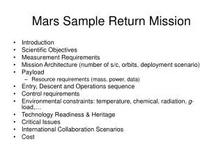
NASA’s Mars Mission Objectives for Next Decade • Embed the Joint ESA/NASA Mars Exploration Program in US and European space agencies • Implement joint ESA/NASA 2016 mission • Trace Gas Orbiter focused science objectives • Entry, Descent, and Landing demonstration • Infrastructure refreshment (telecom) • Begin sample return campaign, 2018 • NASA rover • Focused on collecting high-quality sample return cache with modest suite of high-heritage, low-risk instruments • Solar powered, medium-traverse rover • ESA ExoMars rover focused on subsurface access • Cross-platform sampling highly desirable • Develop key sample return technologies • Joint MSR Working Group to define responsibilities • Plan and initiate the next missions and sequence
Odyssey MRO Mars Express Collaboration Planned MEP Portfolio WITH the Joint Program NASA-ESA Joint Mars Initiative Operational 2018 2013 2011 2016 2020 & Beyond 2009 2001-2007 The Era of Mars Sample Return begins MAVEN Aeronomy Orbiter ESA—NASA ExoMars Trace Gas Orbiter Phoenix (completed) NASA—ESA Rovers (Astrobiology/ Sample Return Cache) Mars Science Laboratory MER "For Planning and Discussion Purposes Only"
Introduction • Concept Studies for Mars Sample Return have been conducted for the last decade (and before) • Architectures examined have varied considerably in cost & complexity from “grab-and-go” with no mobility to concepts with more advanced scientific selectivity in the samples to be returned. • This presentation summarized the approach proposed to the Planetary Science Decadal Survey earlier this year • Involves distributing the task of Mars Sample Return across three flight element launches • Samples returned to a receiving facility (treated as a fourth mission element of the campaign)
Mission Elements Overview Lander collects contingency sample Cache Fetch rover retrieves cache Caching rover deposits cache Mars Ascent Vehicle (MAV) Sky Crane descent Sky Crane descent Orbiting Sample (OS) 500 km orbit Rendezvous and capture of OS MSR Orbiter Caching Mission MSR Lander Earth divert of ERV Sample Receiving Facility (SRF) Earth Entry Vehicle (EEV)
Functional Steps Required to Return a Scientifically Selected Sample to Earth * Launch from Earth/Land on Mars Acquire/Cache Samples Select Samples * Sample Canisters On Mars Surface Sample Caching Rover (MAX-C) ** * Launch Samples to Mars Orbit Retrieve/Package Samples on Mars Mars Sample Return Lander * Orbiting Sample (OS) in Mars Orbit ** * Capture and Isolate Sample Container Return to Earth Land on Earth Orbiting Sample (OS) On Earth • Mars Sample Return Orbiter * Retrieve/Quarantine and Preserve Samples on Earth Assess Hazards Sample Science **Note: Launch sequence of MSR-L/MSR-L can be switched: launching MSR-O first can provide telecom relay support for EDL/surface operation/MAV launch • Mars Returned Sample Handling (MRSH) Facility Sample Science *Artist’s Rendering
Mars Sample Return Discussion - Overview • Multi-element Mars Sample Return Campaign provides robust architecture • Multi-element approach derived from numerous studies • Provides technical robustness and programmatic resilience • Technology challenges for mission elements are identified • Past investments laid ground work for many key required engineering capabilities • Technology tall-poles have been identified: discuss status and development plans that are mapped to mission needs • Other technical challenges also identified
Multi-Element Architecture for Returning Samples from Mars Is a Resilient Approach * * * * Mars Returned Sample Handling Mars Sample Return Lander • Mars Sample Return Orbiter MAX-C (Caching Rover) • Science robustness • Allows robust duration for collection of high quality samples • Technical robustness • Keeps landed mass requirements in family with MSL Entry/Descent/Landing (EDL) capability • Spreads technical challenges across multiple elements • Programmatic robustness • Involves mission concepts with sizes similar to our implementation experience • Incremental progress with samples in safe, scientifically intact states: improved program resiliency • Spreads budget needs and reduces peak year program budget demand • Leverages and retains EDL technical know-how *Artist’s Rendering
Mars Astrobiological Explorer-Cacher (MAX-C) rover • MAX-C rover will perform in situ exploration of Mars and acquire/cache dual sets of scientifically selected samples • Team X conducted Decadal Survey Mars Panel study in Jan’10: added dual cache • Key mission concept features • Cruise/EDL system derived from MSL, launched on Atlas V 531 class vehicle. • Land in ~10 km radius landing ellipse, up to -1 km altitude, within +25 to -15 degrees latitude. • 43% mass margin carried on MAX-C rover (adopting many MSL parts), landing platform, and hardware where specific modifications would be made to the MSL EDL system. Instrument/Sensing Mast Quad UHF Helix High Gain Antenna Low Gain Antenna SHEC “Sample Cache” 2.2m Ultraflex Solar Array Hazard Cameras Sampling/Science Arm * * Artist’s Renderings
Current 2018 Mission Concept Implementation Approach • Team X study concept included: • Landing platform (pallet): ‘proof-of-concept’ by Team X; with further refinements by dedicated design team • Scaling of MSL aeroshell diameter (from 4.5 m to 4.7 m) to accommodate 2 rovers • Preserve MSL shape, L/D • Same thermal protection system • Same parachute • Descent stage architecture/design based on MSL • Same MSL engines, avionics, radar, algorithms, etc • Mechanical structure updated to accommodate rovers/platform geometry/loads • Incorporates terrain-relative descent navigation capability • Land MAX-C and ExoMars rovers together attached to a landing platform • MAX-C and ExoMars rovers perform in situ science exploration: assessing potential joint experiments • MAX-C will cache scientifically selected samples for future return * * MSL Cruise/EDL and Skycrane system lands Rovers on platform * * * * Sample Canisters On Mars Surface MAX-C Rover Rovers post-landing w/ example egress aids * Artist’s Renderings * Artist’s Renderings
Notional Sample Acquisition and Caching Architecture • Tool Deployment Device: • Design: 5 DOF arm • Functions: tool deployment, alignment and linear feed; place canister on the ground. • Coring Tool: • Technique: Rotary percussion; • Functions: Core, breakoff, retention, bit change out, linear spring for preload and vibration isolation. • Caching Subsystem: • Sample Encapsulation: Acquire sample directly into its sample tube in the bit. • Sample Transfer: Use bit changeout to transfer sample to caching subsystem (sample in tube in bit). • Functions: Transfer sample tube in/out of bit, bit changeout, tube sealing, store tubes in canister.
Mars Sample Return Orbiter Concept • Key mission concept features • Over twice the propellant needed by typical Mars orbiters. Uses bi-prop systems flown on previous Mars missions • UHF Electra relay system for surface relay • Orbiter mass quite dependent on specific launch and return years. Designed to envelop opportunities in early-mid 2020s. • MSR Orbiter will • Rendezvous with Orbiting Sample (OS) container in 500km orbit. • Capture, transfer and package OS into Earth Entry Vehicle (EEV) • Perform “break-the-chain” of contact with Mars • Return to Earth • Release EEV for entry • Divert into a non-return trajectory • If Before MSR Lander • Monitor critical events of EDL and MAV launch • Provide telecomm relay for lander and rover * * Team-X Design: Alternate Design: No “staging” required Separate prop stage that separates after Trans Earth Injection * Artist’s Renderings
MSR Orbiter: Sample Capture/Earth Entry Vehicle (EEV) * * * Orbiting Sample (OS) container Capture Basket concept testing on NASA C-9 zero-g aircraft * • Strawman EEV design • 0.9m diameter, 60° sphere-cone blunt body • Self-righting configuration • No parachute required • Hard landing on heatshield structure, with crushable material surrounding OS • Capitalizes on design heritage • Extensive aero-thermal testing and analysis • Wind tunnel tests verified self-righting • Detection and rendezvous systems • OS released into a 500km circular orbit by the MAV • Optical detection from as far as 10,000km. • Autonomous operation for last tens of meters • Capture System • Capture basket concept designed • Prototype demonstrated on NASA zero-g aircraft campaign. * Artist’s Renderings
Mars Sample Return Lander Concept • MSR Lander will • Land a pallet with Mars Ascent Vehicle (MAV) and fetch rover • Upon safe landing, the fetch rover will egress and retrieve MAX-C sample cache • Traverse distance up to ~14 km • Sample cache transferred by robotic arm on pallet from fetch rover to MAV • MAV will launch sample container into stable Martian orbit • Key mission concept features • MSR lander pallet delivered to the surface via the Skycrane EDL approach • Supports and protects MAV in thermal igloo and minimizes thermal cycle depths • 1 Earth year life Lander WEB UHF Ultraflex Solar Array MAV * Fetch Rover Lander arm * Bio-Thermal Barrier Egress Ramps Fetch Rover *Artist’s concept
L D V g MSL EDL Feed Forward To MSR * * • MSL EDL system will deliver ~1000 kg rover to the surface for ‘11 launch • Can be used for MAX-C in 2018 and the MSR Lander in 2020s • Mass of three major sub-elements of MSR lander ~ 1000 kg • EDL performance is relatively constant between 2011 and ‘22-’26 • Can accommodate the MSR Lander • 2018 is a more favorable opportunity than 2011 for EDL • MSL EDL system capability may be improved to accommodate minor increase (~5–10%) to landed mass • Options include increased entry body L/D and parachute deployment Mach number • Three flight-element approach improves resilience for landed mass * Artist’s Renderings
Mars Returned Sample Handling Element Industry studies performed to scope facility and processes (2003) • 3 architectural firms, with experience in biosafety, semi-conductor and food industries. • Current costs estimates and scope based on studies and comparison to existing BSL-4 facilities. Mars Returned Sample Handling element includes: ground recovery operations; Sample Receiving Facility (SRF) and sample curation facility The SRF will • Contain samples as if potentially hazardous, equivalent to biosafety level-4 (BSL-4). • Keep samples isolated from Earth-sourced contaminants • Provide capability to conduct biohazard test protocol as a prerequisite to release of samples from containment. • Could serve as a sample curation facility after hazard assessment. Artist’s concept of an SRF
OS Sealed CV CV Top Impact Sphere Containment Vessel (CV) Orbiting Sample (OS) Earth Entry Vehicle (EEV) CV Bottom Target ”Back PP” Requirements • MSR is a Restricted Earth Return mission • Subsystem requirements: • Break-the-chain of contact with Mars • Deliver a “Mars contained” OS to Containment Vessel (CV) • Assure OS does not “leak” • Mitigate ascent and orbiter dust • Sample container protection • Reliable delivery to Earth entry corridor utilizing a robust Earth Entry Vehicle (EEV) • Assure containment at impact • Maximize OS , CV, and EEV meteoroid protection • Quarantine in specialized sample handling facility and application of a test protocol to assess safety prior to release
Summary • Strong scientific impetus for sample return • Next major step in understanding Mars and the Solar System • Engineering readiness for sample return • Past investments have developed key capabilities critical to sample return • Key remaining technical challenges/development are identified • Resilient multi-flight-element approach • Science robustness • Allows proper sample selection/acquisition • Technical robustness • Spreads technical challenges across multiple elements • Keeps landed mass requirements in family with MSL EDL capability • Programmatic robustness • Involves concepts similar to our existing implementation experience • Scientifically intact samples on/around Mars that provides program resiliency • Spreads budget needs over ~1.5 decade • Approach amenable to international partnership • Multi-element MSR should not be viewed as an “isolated (flagship) mission” but as a cohesive campaign that builds on the past decade of Mars exploration
Sampling System Target RequirementsConsistent with MEPAG Next Decade Science Analysis Group (ND-SAG) • Examples of acceptable samples Science • Acquire~ 20 rock cores with dimension approximately 1 cm wide by 5 cm long • Store and seal samples in individual tubes • Provide capability to reject a sample after acquisition • Measure the sample volume or mass with 50% accuracy Engineering • System mass to be ~30kg • Includes robotic arm • Sample on slopes up to 25 degrees • Sample from a ~300kg rover
Current Sampling Capabilities/State of the Art • Ten years of technology development • MTP, MIDP, SBIR, etc. • Two flight-like corers developed by Honeybee Robotics: • Mini Corer (for ’03/‘05 MSR) • CAT (for MSL) in 2006. • MSL flight drill developed and tested • Drilling and coring testbed developed Honeybee Mini Corer Honeybee CAT (Corer and abrader) MSL Drill Experiments
Strawman Sampling Development Plan • Four end-to-end system concepts are being develop by industry and JPL in FY ‘10 • MEP will select an approach that best fits MAX-C rover architecture and its constraints • Develop sample acquisition and encapsulation capability to TRL 6 prior to MAX-C PDR • Verify system performance via laboratory and rover field tests Alliance Space Systems Concept JPL Concept Honeybee Concept ATK Concept
Planetary Protection Requirements & Mission Scenarios Forward PP Back PP Round Trip PP Outbound to Earth Outbound to Mars Avoid contamination of Mars with Earth life Introduction of viable Earth life into a favorable martian environment is considered harmful contamination by definition Avoid false positive life detection event Life detection event in this context is considered to mean detection of contamination that could be confused with extraterrestrial (ET) life Protect Earth from potentially harmful effects (biohazards)
Current “Back PP” Capabilities/State of the Art • Probabilistic Risk Analysis (PRA) approach was developed to assess the overall probability of meeting the goal • Preliminary design of the EEV was completed and a test article developed. Performed component and system tests: • EEV drop test achieved terminal velocity and demonstrated shock tolerance. • Wind tunnel tests verified aerodynamics, including self-righting. • Arc jet tests verified TPS performance. • A brazing technique was developed to TRL 3 for containment assurance and breaking the chain of contact with Mars • Leak detection • OS leak-detection technique using wireless transducer was demonstrated at TRL3 via an SBIR • Sample container protection • Preliminary materials for OS, CV, and EEV to assure meteoroid protection were selected (TRL 2-3 development).
Strawman “Back PP” Development Plan • Update/improve models for Probabilistic Risk Analysis (PRA) to measure capability to meet goal • Breaking-the-chain • Investigate various options of sealing the OS in a container. Will implement and evaluate prototypes • Down select and develop technology to TRL 6. Test and verify sealing • Develop OS leak detection technique by considering pressure drop or other techniques • Down select and develop technology to TRL 6 • Sample container protection • Update EEV design considering the availability of TPS material • Perform impact, heat, and aerodynamics tests • Select materials for OS, CV, and EEV and satisfy meteoroid protection requirement • Assure containment and sample integrity during ground processing • Sample transfer from landing site to Sample Receiving Facility • Ultra-clean sample manipulation, double-walled glove boxes