Download
1 / 17
170 likes | 309 Views
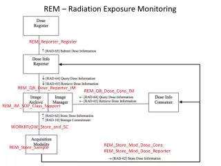
D0SMT Radiation Monitoring. Contents: Radiation effects in silicon and impact on RunIIb Dosimetry techniques The BLM system The finger diode system TLDs and foils Detector currents Results so far. Depletion voltage (volts). Neutron fluence (10 13 /cm 2 ). N eff (10 11 /cm 3 ).

E N D
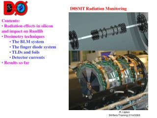
D0SMT Radiation Monitoring • Contents: • Radiation effects in silicon and impact on RunIIb • Dosimetry techniques • The BLM system • The finger diode system • TLDs and foils • Detector currents • Results so far
Depletion voltage (volts) Neutron fluence (1013/cm2) Neff (1011/cm3) Neutron fluence (1013/cm2) Radiation effects on Silicon • Two major effects • Increased leakage current • More noise • Possible thermal runaway • Increase in Depletion voltage • Increases operating voltage of detectors • Change sensors from n to p type silicon • Will cause breakdown of coupling capacitors, microdischarge breakdown of p-n junction Both depend on temperature
BLM System • BLM system • copy of run 1/current CDF system • Interfaced to beam abort – this is what currently dumps the beam • Far from silicon (downstream of calorimeter), large extrapolation to silicon dose. • Integral not very sensitive to small, continuous dose due to integration thresholds. • Logarithmic response – odd behavior and quantized jumps at low dose rates • Technical: • 8 glass ion argon ion chambers (coke bottles). • Very simple devices – no gain – integrate total charge • Large dynamic range – log amp in chassis • Processing in 2 CAMAC modules C336/C337 – do inversion of log response, keep rolling sums and fast FIFO buffer than can be dumped if the beam is aborted to examine dose at millisecond time scale
BLM Readout Chassis circuit
BLM ACNET BLM Variables Alarms and limits • Rate/sec : D0BLXX • Integrated dose: D0BRXX • Rate/min: D0BAXX (set) • FIFO: D0BFXX • Locations: • UT – Upstream top (P side)(monitored by MCR) • UB – Upstream bottom • UI – Upstream inner • UO – Upstream outer • D - downstream
BLM Calibration • Our initial calibration found that the dose rate CDF was using for Run I was off by a factor of 7! Not a perfect system by any means… Integral and rate response at 0.5 na. Normalized response BLM integral and rate response as a function of current Integral and rate response at 70 na.
The Finger Diode System • Detectors- 24 one cm photodiodes at 4 radii • Provide MIP signals • Three electronics paths • Single particle scalers (thresh ~ 2.5 MIPs) • High gain integration • Low gain integration • Data fed to EPICS – not yet used for beam abort • Dynamic range from mrads/sec to Krads/sec • Original ADC system not sensitive to small losses – add scalers
Fingers during Shot Setup ADC Output Scaler Output
Readout • MCH3 2 VME crates • ADCs and scalers + NIM logic • Devices sensitive to noise during SMT readout • ADC jumps – solve in software? • Large scaler count rate – solved by gating
Finger Diode III Dose rates Temperatures New finger GUI The radmon Gui Watch these Online crate alive HV for BLMs (1500<HV<2200)
Finger GUI Makes ps file /projects/D0smt/radmon/RADMON_north_yyyymmdd_hhmmss.ps The radmon Circle plots Wherever North is mentioned als South applies Disabled Colour coding of bars (self explanatory) Resize Inner two circles: F-disk Fingers; Outer two circles: H-disk Fingers Minimal height To show position Outside ring positive value, inside negative (noise) Max scale between circles is 1 Rad/s, scale linear
Finger Archiver • To look at data from the SMT finger channel archiver: > cd /projects/archive/radmon/current > ls 20011217-000000 archive_active.lck dir.20011217-095540 radmon_rad_low.cfg 20011218-000000 cfg log radmon_scaler.cfg 20011219-000000 config_file radmon_rad_high.cfg radmon_temp.cfg 20011220-000000 core radmon_rad_int.cfg > setup d0online **** setup D0RunII t01.67.00 > setup chan_archiver > Xarr.py dir.20011217-095540 & !paste name of current directory You then enter device names in the Xarr window, * can be used as a wild card. Names are: SMT_FINGER_AAANNN/XXX • Where : • AAA: IFN, IFS, OFN, OFS, IHN, IHS, OHN, OHS • I: inner radius device O: outer radius device F: F Disk H: H Disk N: North S: South NNN: finger angle (12:00 = 0 degrees) • F: 45,105,165,225,285,345 H: 0,60,120,180,240,300 XXX: RATE,RLVH,RLVL,INT • RATE: scaler rate ~ 1/3 x MIP rate (working channels) INT : rolling sum of scaler rate. RLVH: Calculated dose rate from currents, high gain channel RLVL: Calculated dose rate from currents, low gain channel
Finger Diode II Typical store – shot setup and normal running Effects of looping tracks on silicon Dose - compare with CDF at 1.5 T
Contributions of Luminosity and Halo Technique – losses during a store have different shapes for halo and luminosity. Normalize to mid –store and fit finger rates to shapes of the luminosity and p/p halo rates. This gives us a rough idea of how losses contribute to irradiation. Rates for store 2121. Fit is to pbar, p halo and luminosity
TLDs • TLD 600 (b, g and neutrons) • TLD 700 (b, g only) • Calibrated to few % but only linear to ~ 5-10 Krad • Added Al foils to integrate larger doses (1 year) • Installed removable system during shutdown
Dose estimate • Particle flux as calculated from leakage current increase as a function of radius. Correct for temperature, area, annealing … • Errors on the D0 points are statistical only