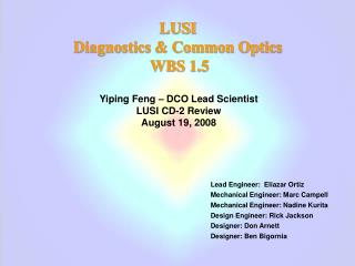
LUSI Diagnostics & Common Optics
720 likes | 740 Views
This overview highlights the crucial X-ray diagnostics and common optics suite for Free-Electron Laser (FEL) beam conditioning, encompassing intensity and wavefront monitoring, along with slits diagnostics. These tools play a pivotal role in measuring fluctuations and facilitating high-resolution experiments. The X-ray Common Optics Suite features devices for peak power sustainment, coherence preservation, and pulse manipulation across all LUSI instruments. The Front-End Enclosure and Experimental Halls house the X-ray Transport Tunnels, accommodating instrument-specific needs and beam manipulations. The Intensity-Position Monitor, Wavefront Monitor, and Slits validations, underpinning the FEE Diagnostics, showcase the requisite device concepts and implementations critical for beam evaluations. These sophisticated systems ensure precise X-ray manipulation and experimental success.

LUSI Diagnostics & Common Optics
E N D
Presentation Transcript
LUSI Diagnostics & Common Optics Facility Advisory Committee XTOD/XES/LUSI Breakout June 16-17 2008 • Overview • Intensity-Position Monitor • Wavefront Monitor • Slits
Diagnostics Overview • X-ray Free-Electron Laser (FEL) is of fundamental differences from storage-ring based synchrotron sources • At LCLS, it is Linac-based, single-pass, operating at 120 Hz • Feedback is limited by low repetition rate • Each macro electron bunch is different in timing, length, density, energy (velocity), orbit, emittance, etc. • At LCLS, the self-seeding SASE is responsible for X-ray amplification process • Lasing starts from a random electron density distribution • Each X-ray pulse consists of a random time sequence of spikes of varying degrees of saturation • LCLS X-ray FEL exhibits inherent intensity, spatial/modal, temporal/spectral, & timing fluctuations on pulse by pulse basis
Diagnostics Objectives • X-ray diagnostics are required to measure these fluctuations • Integral parts of Instruments • High-resolution intensity measurements for XPP experiments • Wavefront characterization for CXI/XCS experiments • Measurements made on pulse-by-pulse basis • Requiring sophisticated data acquisition system • Commonalities in needs & specs • Standardized and used for all applicable instruments • Modularized for greater flexibilities • All diagnostics must be performed and measurement data made available on pulse-by-pulse basis if needed
Common Optics Overview • Driven by Common Experimental Needs & Performance Requirements • X-ray optics to manipulate pulses delivered to sample • Shaping & cleaning • Attenuation • Pulse pattern alteration or repetition rate reduction • High harmonic rejection • Focusing • Common requirements • Must sustain peak power when used in pink beam • Average thermal load is small (< 1 W, i.e. no cryogenic cooling) • Preserve coherence to the extent possible • X-ray Common Optics needs and requirements are shared by all LUSI instruments, leading to common design, and implementation
Front End Enclosure Near Experimental Hall (XPP) X-ray Transport Tunnel (CXI, XCS) Far Experimental Hall (CXI, XCS) LCLS
X-ray Optics and Diagnostics in FEE • Designed primarily for FEL beam conditioning, commissioning, and global measurements
Diagnostics/Optics Scope Far Experimental Hall • Diagnostics/Common Optics • Scope include: • XPP Instrument • CXI Instrument • XCS Instrument • X-ray Transport Tunnel CXI Endstation X-ray Transport Tunnel XCS Endstation Near Experimental Hall XPP Endstation AMO (LCLS) • Designed primarily to meet instrument specific (local) needs for beam manipulations and experimental measurements • Use FEE optics and diagnostics when appropriate FEE
Diagnostics/Optics Status • Numbers in parentheses are for when mono is in scope by BCR
Diagnostics Summary Specifications * Must have high damage threshold
Device Concepts/Implementations • Needing FAC feedbacks/recommendations • Intensity-position monitor • Validation of concept • Risk assessment & mitigation • Wavefront monitor • Validation of concept • In lieu of Hartmann wavefront monitor • Performance expectations • Slits • Validation of concept • Material selection • Risk assessment & mitigation
Intensity-Position Monitor • Physics Requirements • Primary Purpose • Intensity measurement of incident X-ray • In-situ, non-destructive • If in transmission geometry, transmissivity > 95% • Energy range from 2 to 25 keV • 0.1% accuracy if permitted by Poisson counting statistics • Dynamic range of > 1000 • Per pulse operation • 2x2 mm2 working range • Secondary Purpose • Beam position monitoring w/ use of array detectors • x,y positions to < 5 mm • Pointing in x,y to < 5/L mrad w/ two monitors separated by L meters.
Intensity-Position Monitor • System concept • Incident intensity measurement • Scattering from target material • Ability to withstand the peak fluence of an unfocused X-ray FEL beam. • Highly transmissive in the operating range of 2 keV to 8.3 keV (w/ 3rd harmonic from 6 to 25 keV). • High Compton scattering cross-section to enhance back scattering. • Low photoelectric cross-section, but high scattering cross-section. • Availability in thin free-standing foil form with sufficient mechanical rigidity. • High density uniformity and small surface roughness so it will not become a phase object and relatively free of absorption edges. • Preferably in amorphous state • Position/pointing measurement • Use array detectors (at least 4 in quadrature configuration). • Normal incidence preferred by resolution considerations • Use large separation between monitors for high angular resolution.
Quad-Detector R2 q1 q2 R1 Target L Conceptual Design- Back Scattering Geometry FEL • Monolithic design • Expensive fabrication • High collection efficiency • Four-diode design • Readily available/easy assembly • Less collection efficiency/difficult to model
Material vs. Energy & Peak Intensity NEH FEH Peak Intensity X-ray energy FEH NEH safe threshold actual intensity threshold operating energy safe Effective atomic number Z Effective atomic number Z • the smaller the Z, the safer • the higher the energy, the safer • the FEH is safer if no additional focusing • the smaller the Z, the safer • the lower the peak intensity, the safer • the FEH is safer if no additional focusing
Option 1: Beryllium • Assuming 2 mJ/pulse for all energies • Gaussian beam, w0 is waist at z • Source point at 1 Rayleigh length upstream of down stream end of undulator
y x ê┴ ê|| ê0 k k0 z f q Scattering Processes • Scattering signals • Compton scattering • Higher cross-section in back scattering geometry • The lower the Z, the higher the cross-section • Thomson scattering • Mostly in the forward direction • Proportional to Z2 • K-fluorescence • Negligible at low Z • Photoelectrons • Primary electrons • Auger electrons
Calculated Performance • At 25 mm for 2keV, the transmission is only 71%
Risks/Mitigations • Beryllium is all most ideal, but • Glitches from diffractions (power rings, Bragg/Laue) • Affect intensity/position measurement accuracies • Use amorphous materials • Si3N4, but damage issues below 4 keV • Smaller signal • Capability loss • Use diamond single crystal • Expensive • Sub-mm at 2 keV for 95% transmission • Somewhat smaller signal
Foil Thickness 8.265 keV 8.265 keV Be B4C C YAG Si3N4 Si
Alternative Concepts • Commercial fluorescence monitor* • using similar design provides equal resolution • but not viable due to damage considerations • Must use material w/ Z > 20 • CVD diamond BPM** • Good from damage point of view • Based on photoconduction • Large band gap, somewhat smaller signal • design more complex in fabrication • Electrodes on diamond, must be in direct path of FEL • Prone to damage • Small working range ~ order of beam size • Expensive *R.W.Alkire et al J. Synch. Rad. (2000), 7 (61-68); Oxford-Danfysik, QBMP **P. Bergonzo, et al J. Synch. Rad. (2006), 13 (151-158)
Wavefront Characterization • Characterization of wavefront of a focused X-ray FEL is a challenge • Critical to CXI experiments if atomic resolution is ultimately to be achieved • Wavefront distortion must be backed out in phase retrieval algorithm • Common scanning or direct imaging techniques made at focus not viable due to FEL high peak power plane wave assumed
Hartmann Wavefront Sensor • Hartmann wavefront sensor technique was considered viable • Measurement made far from focus • Focal point determination calculated from radius of curvature measurement • Wavefront distortion obtained by back-propagation of diffracted wave-front determined at mask plane • Commercial Hartmann wavefront for long wavelength • Successful in optical applications (adaptive optics, etc.) • For X-ray applications • X-EUV sensor for energy up to 4 keV • Prototype for hard X-rays up to 10 keV • Image acquisition < 120 Hz
Hartmann Wavefront Sensor (con’t) • Challenges • Working at > 8 keV • Tighter technical specs at shorter wavelength • Holes on mask must not work as waveguides • Could use grids instead • Mask materials must withstand FEL peak fluence • 120 Hz operation Divergent wavefront Algorithm Image obtained from Imagine Optics, Ltd modal/zonal reconstruction algorithms
2D Detector Attenuator Detector Focal Plane Focusing Optic FEL Beam w0 W f L Diffractive Wavefront Reconstruction • The oversampled diffraction pattern of the focus is measured. • The focal spot is iteratively reconstructed using phase retrieval methods by propagating the wave from the optic to the focus and then to the detector plane. • The constraints are applied at the optic and detector planes. H. M. Quiney et al. Nature Physics2, 101 - 104 (2006)
Wavefront Monitor • Physics Requirements • Primary Purpose • Characterizing 2D intensity profile of a focused FEL beam • Capturing 2D beam profile far away from focal point • Large FOV of 40x40 mm2, 165 mm • Medium FOV of 8x8 mm2, 33 mm • Small FOV of 1.2x1.2 mm2 , 5 mm • Intensity levels, 1024 or 10 bits, w/ goal of 4096 or 12 bits • Per-pulse operation • Attenuation whenever appropriate in high fluence • Secondary Purpose • Measurement of complimentary low-Q data for diffraction experiments • Large dynamic range desired
Wavefront Monitor 45º mirror working distance YAG:Ce screen Zoom lens 120 Hz CCD camera
Imaging System 45º geometry Optical CCD Camera w/ zoom lens Dx t q f Dx = tsin(f)/cos(q) Working distance 45º mirror X-ray pulses Scintillator Virtual image
YAG:Ce scintillation screen High radiation hardness High melting temperature High thermal conductivity In NEH & FEH, capable of sustain full unfocused X-ray FEL beam at normal incidence Fast scintillator moderate optical fluorescence yield Peak response (550 nm) matches optical CCD QE curve High spatial resolution Capable of normal incidence Clear, not diffuse as phosphor Vacuum compatible Summary characteristics Key Components
Size The bigger, the thicker 25x25 mm2 , 75 mm 12x12mm2 , 50 mm Thickness Affect resolution achievable < Depth of field Requiring telecentric lens if too thick Thickness limited for free standing crystals >= 50 mm Thinner sample will be based on epitaxial YAG:Ce on YAG substrate ~ 5 mm possible But YAG glows as well YAG:Ce Selection YAG:Ce crystal YAG crystal 5 mm YAG:Ce epitaxial layer
Parallaxial distortion Diffusive broadening YAG:Ce Resolution r t t Z1 f Ddiff Dpara Ddiff = at Dpara = -Mtr/(z1-f)
Transmission & QE YAG Quantum Efficiency = 1-Transmission = 70% @ 10 keV @ 75 mm
Damage Consideration • Attenuation needed for low energies in NEH-3
Navitar Large Zoom lens Modular design Attachment+zoom+adapter Flexible to achieve diverse requirements Large range of FOV 12x Maintaining focus while zooming Fixed working distance 165 mm Sufficient numerical aperture for good resolution NA ~ 0.05 – 0.2 Readily Motorized Focus or zoom or focus&zoom Zoom Lens System Motorized Zoom Lens Zoom Lens adapter zoom attachment
Imaging ½ inch optical CCD - Pulnix TM-6710CL Optimal response at 600 nm w/ QE ~ 30% 648x484 pixels Progressive scan @ 120 Hz 9.9 mm square pixels 8 bits Cameralink Frame grabber supported on Linux OS Digital Camera
Expected Performance • Wavefront measurement in FEH-5 – 0.1 mm KB (in Q space) 40 mm FOV, waist = 27x50 pixels (0.1 mm focusing @ FEH-5 @ 5 m from focus) 10 mm FOV, waist = 110x198 pixels (0.1 mm focusing @ FEH-5 @ 5 m from focus) • 188 Å resolution, 4.5 mm FOV, 242 resolving power • Revealing features outside of focal region
Expected Performance • Wavefront measurement in FEH-5 – 1.0 mm KB (in Q space) 8 mm FOV, waist = 32x34 pixels (1.0 mm focusing @ FEH-5 @ 11 m from focus) 2 mm FOV, waist = 128x135 pixels (1.0 mm focusing @ FEH-5 @ 11 m from focus) • 2063 Å resolution, 50 mm FOV, 242 resolving power • Revealing features outside of focal region
Expected Performance • Wavefront measurement in FEH-5 – 10 mm Be Lens (in Q space) 1.2 mm FOV, waist = 22x22 pixels (10 mm focusing @ FEH-5 @ 11 m from focus) 800 mm FOV, waist = 33x33 pixels (10 mm focusing @ FEH-5 @ 11 m from focus) • 1.38 mm resolution, 333 mm FOV, 242 resolving power • Revealing features outside of focal region
Slit System • Slit systems requirements • Variable horizontal and vertical gap from -.1 μm – 10 mm • Can withstand full LCLS flux – unfocused • Minimize background scatter from blades
Slits System Design D. Le Bolloc’h et al., J. Synchrotron Rad., 9, 258-265 (2002). Offset in Z to fully close But asymmetry in near field Pink beam Low-Z High-Z Mono beam D=3 mm Slit-round blades High-Z
Wavefront Simulationfor XPP by S. Boutet HOMS (treated simply as an aperture) Lenses Slit 2 Slit 1 Source 105.8 m Distance depends on photon energy 32.4 m 0.597 m Undulator Exit 2.613 m 1.487 m
2 keV Through 20 micron Ta 1st SlitThrough 3 Lenses, Through 30 micron Ta 2nd Slit
Material Selection • Only materials that survive the beam at 2 keV • B, Be, BN, Diamond and Li • No good options • Only materials that survive the beam at 4 keV • Al, B4C, B, Be, BN, Diamond, Li, Mg, Si3N4, YAG, ZnO • Si3N4 looks good • Double blades only useful if placed very close to the sample (<< 1 m)
Proposed Solutions • Use Si3N4 for Guard slits • Always safe in FEH • Only above 4 keV in NEH without attenuation • Use Ta for Mono slits • Since Si crystals for the monochromators will not survive the beam in the NEH, we will have to use diamond • Ta is safe above 3keV for mono beam with Diamond (220) • Use Si3N4 as 1st blade for Primary slits • Ta for 2nd blade • Requires a 4±1 micron offset of the 2nd blade
Summary • Diagnostics • Focused on key FEL attributes that impact the success of LCLS scientific programs • Characterizing inherent LCLS fluctuations • Common mechanical interface allows flexibilities • X-ray common optics • Enabling users to manipulate/shape FEL beam to maximize scientific output • Designed to preserve FEL characteristics • Transverse coherence • Common design & implementation
Physics Instrument Jerry Hastings David Fritz Aymeric Robert Sébastien Boutet Marc Messerschmidt Niels van Bakel John Bozek Accelerator, XTOD, and FEL Physics John Arthur Paul Emma Zhirong Huang Peter Steffen XTOD team Engineering System Nadine Kurita Eliazar Ortiz Paul Montanez J. Brian Langton Donald Arnett Jean-Charles Castagna Jim Defever Jim Delor Rick Jackson Nicolas Reeck Controls/Data Systems Gunther Haller Dieter Freytag Steffen Luitz David Nelson Amedeo Perazzo Raymond Rodriguez Contributors