Electromagnetic Induction
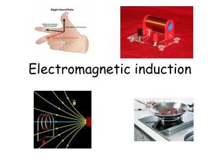
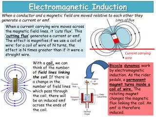
Electromagnetic Induction. When a conductor and a magnetic field are moved relative to each other they generate a current or emf. When a current carrying wire moves across the magnetic field lines, it ‘cuts flux’. This ‘cutting flux ’ generates a current or emf.

Electromagnetic Induction
E N D
Presentation Transcript
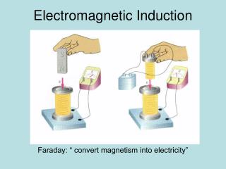
Electromagnetic Induction When a conductor and a magnetic field are moved relative to each other they generate a current or emf. When a current carrying wire moves across the magnetic field lines, it ‘cuts flux’. This ‘cutting flux’ generates a current or emf. The effect is magnifies if we use a coil of wire: for a coil of wire of N turns, the effect is N times greater than if it were a straight wire. Lines of flux With a coil, we can think of the number of field lines linking the coil. If there is a change in the number of field lines which pass through the coil, there will be an induced emf across the ends of the coil. Bicycledynamoswork by electromagnetic induction. As the rider pedals, a permanent magnet turns inside a coil of wire. The rotating magnet changes the magnetic flux linking the coil. An emf is therefore induced. Current carrying wire
The direction of the induced current can be determined using Fleming’s Right hand dynamo rule. Thumb = direction of motion First Finger = direction of magnetic field Second Finger = direction of conventional current. Faraday’s Law of Electromagnetic Induction states that the magnitude of an induced emf is proportional to the rate of change of magnetic flux linkage. Magnetic Flux is equal to the magnetic flux density multiplied by the area: Magnetic flux linkage is the product of the magnetic flux and the number of turns: Φ = BA BAN = NΦ
Lenz’s Law According to Lenz’s Law, any induced current or emf will be established in a direction as to produce effects which opposes the change that is producing it. When a magnet is pushed into a coil of wire, there is an induced current. The current in the coil turns it into an electromagnet. One end becomes a North pole and one end becomes a South pole. The below is correct. The ends of the magnet and electromagnet must repel, otherwise the poles would be attracted to each other, the magnet would accelerate into the coil and we would be gaining energy without putting energy in. Lenz’s Law follows from the law of conservation of energy: energy must be transferred to produce an induced current – so work must be done to make the change which causes it. Here, the poles of the electromagnet and permanent magnet repel each other. We have to do work to push the magnet into the coil. The energy transferred is equal to the electrical energy of the current, so the principle of conservation of energy is not violated. South Pole North Pole S N
Using Induction: AC Generator In an AC generator, a coil is rotated in a magnetic field. This induces an EMF in the coil so a current flows. The current keeps changing direction as the coil faces first one way then the next. • When the flux linked is at a maximum, the rate of change of flux linkage is 0 and hence the induced emf is 0. • When the flux linked is at a minimum, the rate of change of flux linkage is at a maximum and hence induced emf is at a maximum.
Transformers Transformers use electromagnetic induction in order to increase or decrease an output voltage. • A sinusoidally varying current through the primary will produce a sinusoidally varying flux through the primary. • The soft iron core is magnetised and carries the flux to the secondary. • The varying flux through the secondary, according to Faraday’s Law, produces an alternating (sinusoidally varying) emf across the secondary coil. A step up transformer has more turns on the secondary than the primary. Flux linkage is proportional to the number of turns, so there is more flux linkage on the secondary coil, and hence, as the induced emf is proportional to the rate of change of flux linkage, the induced emf across the secondary will be greater than the voltage across the primary. Step down transformers have fewer turns on the secondary coil, so that the induced emf cross the secondary coil will be less than the voltage across the primary coil. VpIp= VsIs In practice, transformers waste energy as heat due to resistance of the coils and eddy currents produced by the changing flux. The core is laminated to reduce this.