Direct Link Networks in Computer Networking
890 likes | 967 Views
Explore OSI DataLink and TCP/IP Host-to-Network layers, including encoding, framing, error detection, link reliability, and access mediation. Study low-level issues in network technologies like point-to-point links, CSMA networks, Token Ring networks, and wireless networks. Learn about node connections, memory, and links in networking architecture. Discover cable types like twisted pair, coaxial, and optical fiber used in network installations.

Direct Link Networks in Computer Networking
E N D
Presentation Transcript
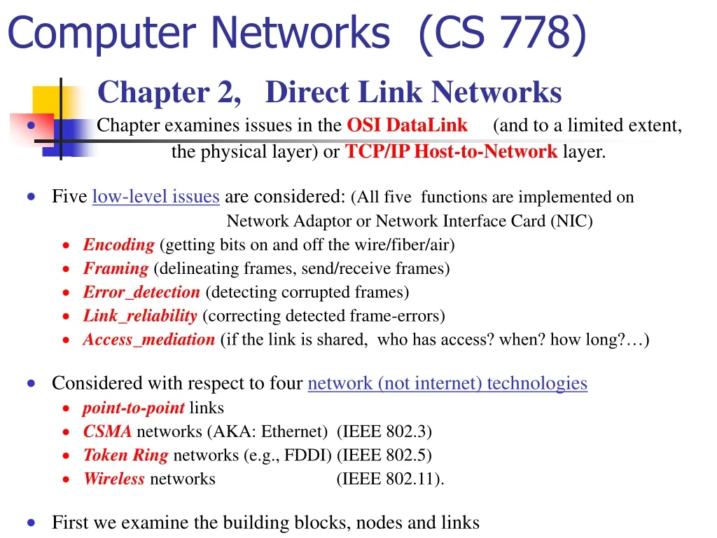
Computer Networks (CS 778) Chapter 2, Direct Link Networks • Chapter examines issues in the OSI DataLink (and to a limited extent, the physical layer) or TCP/IP Host-to-Network layer. • Five low-level issues are considered: (All five functions are implemented on Network Adaptor or Network Interface Card (NIC) • Encoding (getting bits on and off the wire/fiber/air) • Framing (delineating frames, send/receive frames) • Error_detection (detecting corrupted frames) • Link_reliability (correcting detected frame-errors) • Access_mediation (if the link is shared, who has access? when? how long?…) • Considered with respect to four network (not internet) technologies • point-to-point links • CSMA networks (AKA: Ethernet) (IEEE 802.3) • Token Ring networks (e.g., FDDI) (IEEE 802.5) • Wireless networks (IEEE 802.11). • First we examine the building blocks, nodes and links
Nodes(assume general purpose computers (workstations) • Altho internal nodes (switches) are usually special purpose. • Finite memory (implies limited buffer space) • Connects to network via a network adaptor • Fast processor, slow memory Three key features of workstation (for networking): 1. MemoryScarce resource in switches/routers (the other is bandwidth) 2. Network adaptor(on I/O bus; delivers data to the network link) • device driver: software on workstation which issues commands to adaptor 3. CPU (capacity increasing rapidly - not true of memory) CACHE: (level-1: on chip (holds instructions, parameters... ~64KB); level-2: (SRAM; ~512KB) MAIN MEMORY: (DRAM, MMs range 64MB - 128MB - 512MB - 1GB - 10GB …) • Random-access=(any byte has same access time) • Working memory of most computers. Designs unchanged but in 10 yrs, chip-capacity has increased 256Kb - 256 Mb... Speed of DRAM has not increased Processor speeds are doubling every 18 months • Memory speeds are increasing at 7% per year. • Thus a node runs at memory speeds, not processor speeds. • Thus, net software must care about memory access How many times memory is accessed per message is important.
Links If you install your own. If nodes are in same room, bldg or site(campus), buy cable and physically string it between nodes. What type of cable? Sometimes links are leased from the phone company (STS is also denoted OC)
Twisted Pair - Transmission Characteristics • Limited distance / bandwidth / data rate • Susceptible to interference and noise • Analog (Amplifiers every 5km to 6km) • Digital (Use either analog or digital signals, repeater every 2km or 3km) • Unshielded Twisted Pair (UTP) • Ordinary telephone wire • Cheapest • Easiest to install • Suffers from external EM interference • Category 3(up to 16MHz; Voice grade found in most offices; Twist length 7.5 cm to 10 cm) • Category 4(up to 20 MHz) • Category 5(up to 100MHz ; Commonly pre-installed in new office bldg; Twist length 0.6-0.85 cm • Shielded Twisted Pair (STP) • Metal braid or sheathing that reduces interference • More expensive • Harder to handle (thick, heavy)
Coaxial Cable Applications and characteristics • Most versatile medium • Television distribution • Antenna to TV • Cable TV • Long distance telephone transmission • Can carry 10,000 voice calls simultaneously • Being replaced by fiber optic • Short distance computer systems links • Local area networks • Analog • Amplifiers every few km • Closer if higher frequency • Up to 500MHz • Digital • Repeater every 1km • Closer for higher data rates
Optical Fiber Benefits and Applications • Greater capacity (Data rates of hundreds of Gbps) • Smaller size & weight; Lower attenuation; Electromagnetic isolation • Greater repeater spacing (10s of kms at least) • Applications ( Long-haul / Metro / Rural-exchange Trunks; Subscriber loops; LANs) (Varied index of refraction of the core so laser beams don’t interfere with each other as much )
ElectroMagnetic Waves (EM) Signals use electromagnetic (EM) waves traveling at the speed of light (medium-dependent: copper and fiber about 2/3 of that in a vacuum) freq 10^X Hz 0 2 4 6 8 10 12 14 16 18 20 22 24 .--+----+----+----+----+----+----+----+----+----+----+----+----+----. | |Radio |Microwav|Infrared |UV | Xray |Gamma ray| `-------------------------------------------------------------------’ wavelen (nm) / ^ \ ___________/ | \__________ / visible. \ / `---. \ / Radio | Microwave | InfraRed || UV \ <-+----+----+----+----+----+----+----+----+----+----+----+----+ >10^ 4 5 6 7 8 9 10 11 12 13 14 15 16 <satellite > <-fiber> <----Coax------ > <AM> <FM> <terrestial> microwave <-TV > • Binary data is encoded on EM signal thru modulation • Signals propagate over a physical medium - modulate electromagnetic waves - e.g., vary voltage • Modulation = varying signal frequency/ampl/phase to effect the transmission of info. • e.g., vary power (amplitude) of signal (turn hi/low)
Microwave • Terrestrial (Parabolic dish, Focused beam, Line of sight, Long haul telecommunications, Higher frequencies give higher data rates) • Satellite • Satellite is relay station - receives on one frequency, amplifies or repeats signal and transmits on another frequency • Requires geo-stationary equitorial orbit (Height of 35,784km = 22,365 mi.) • USES: Television, Long distance telephone, Private business networks BROADCAST RADIO • Omnidirectional • FM radio • UHF and VHF television Infrared • Line of sight (or reflection) • Blocked by walls • e.g. TV remote control, IRD port
Services • For pt-pt links two bit streams may be able to concurrently transmit in opposite directions (full duplex) or one direction at a time (half duplex). • Assume links are full-duplex unless stated otherwise. Common Services to the home (last mile) Service Bandwidth POTS 28.8 - 56 Kbps (POTS uses a modem for data (modulator/demodulator) ISDN 64 - 128 Kbps xDSL 16Kbps - 55.2Mbps CATV 20 - 40 Mbps Shannon's theorem limits modem rate over analog phones. • C = B*log2(1+S/N); C=achievable channel cap in Hz • B=bandwidth (3300Hz-300Hz = 3000 Hz) • S = Average signal power; N = Average noise power • Current POTS, S/N=1000 • Thus, C = 3000 * log2(1001) =~ 30Kbps • Why are 56Kbps modems available then? • 1. line qualities improving ( N is lower) • 2. 3300Hz-limited Analog lines are being upgraded
Services (cont.) ISDN (Integrated Service Digital Network) - 2 64-Kbps channels (1 = digitized voice, 1 = data) - CODEC (coder/decoder) en/de-codes voice <--> digital xDSL (Digital Subscriber Line) Collection of technologies able to transmit data at high speeds over twisted pair copper found in homes. • ADSL(Asymmetrical Digital Subscriber Line) • (Asymmetric) different upstream (phone-to-CO) and downstream (CO-to-phone) rates. • Rates depend on length of link phone -CO (local loop) • downstream: 1.544 Mbps (3.4 mi.) to 8.448 Mbps (1.7 mi.); upstream: 16 Kbps to 640 Kbps • VDSL(Very-high-data-rate) will be symmetric • 12.96Mbps - 55.2Mbps (1000 - 4500 ft.) (Won't reach from home to CO!) • Phone CO must put STS-n fiber from nbhd to CO ("fiber to the home" or "fiber to the curb" - several homes). • CATV reach ~95% of US homes (~65% subscribe) • some subset of CATV channels (each at 6 MHz) is for digital data. • CATV cable modems are used asymmetrically (40-100Mbps downstream, 20-50Mbps upstream on 1 channel) • (bandwidth will be shared by all users in nbhd requiring some MAC like CSMA/CD or?). • Wireless Links (All 3 use towers) • AMPS (Adv Mobile Phone Sysyem) standard for US cell phones (analog). • PCS (Personal Communication Service), digital cellular, gaining in US. • GMS (Global Mobile System) digital cellular in rest of world. LEO/MEO constellations (Low/Med Earth Orbit) Project | Orbit |Sats |Uplink Freq| Downlink Most are voice ===========|==km======|======|==MHz======|========== Potential for 2 Mbps link ICO |10,355 | 10 | 2170-2200 |1980-2010 Globestar | 1,410 | 48 | L-band |S-band Iridium | 780 | 66 | L-band |L-band Teledesic | 1,350 | 288 | Ka-band |Ka-band Each sattelite will support 1440 16-Kbps satellite-to-earth channels, which can aggregate in a group of 128 to provide 2.048-Mbps inter-satellite channels.
Services (wireless) Wireless Links • Radio (RF) and IR can be used for short links (e.g., office bldgs, malls, campuses) • IR (850-950 nm) provides 1 Mbps over 10 meters. (does not require line-of-sight) • RF bands being made available for data comm (5.2 & 17 GHz for HIPERLAN (Hi Perf European Radio) 2.4 GHz for IEEE 802.11 wireless LANs. • Bluetooth RF (Ericsson, Nokia, IBM, Tohsiba, Itel) • at 2.45GHz (dis = ~10 m) 1 Mbps for eg, printers, • workstn, laptop, projector, PDA, mobile phone; • eliminating wires and cabling in the office. • Networks of such devices are called Piconets. Iridium satellites form 6 neckaces around earth 1628 moving cells cover the earth.
Bits 0 0 1 0 1 1 1 1 0 1 0 0 0 0 1 0 NRZ Encoding • Encode binary data onto signals Non-Return to Zero (NRZ) (0 as low signal and 1 as high) • 2 Problems with long strings of consecutive 1s or 0s • Long string of High signals (1) leads to baseline wander (receiver keeps an average to distinguish hi/lo – consecutive strings shift that average) • Unable to recover clock (Clock is not transmitted over a separate wire, but is integrated into the data signal – cycle boundaries are used to re-synchronize clocks). • A link attribute = Number of bit streams that can be concurrently encoded on it. • If just 1, then nodes must share access to the link • (eg CSMA/CD, Token-Ring Multiple Access Protocol) An Aside on SHARED RESOURCE MANAGEMENT • WAITING POLICY: If needed resource is unavailable, requester waits til it becomes available. • This is how print jobs are managed by an OS • RESTART POLICY: If needed resource is unavailable, the requester terminates and retries later. • This is one way network channels are managed: Ethernet (unswitched) CSMA/CD. • Encoding (NRZ, NRZI, Manchester, 4B/5B) • Assume 2 discrete signal: high and low (ignoring modulation concepts and issues) • Most functions are performed by Network adapter which encodes/decodes bits in signals.
Bits 0 0 1 0 1 1 1 1 0 1 0 0 0 0 1 0 NRZ Clock Manchester NRZI Alternative Encodings • Non-return to Zero Inverted (NRZI) • Make transition from current signal to encode 1. Stay at current signal to encode 0. • Solves the problem of consecutive ones. • Manchester (transmit XOR of NRZ and clock (50% efficient) • Doubles rate of transitions. Receiver has half as much time to detect. • In Manchester, bit-rate = 1/2 baud rate • (50% efficient; rate of signal change = baud rate) (rate of signal change is baud rate)
Encodings (cont) • 4B/5B • every 4 bits of data encoded in a 5-bit code • 5-bit codes selected to have no more than one leading 0 and no more than two trailing 0s • thus, never get more than three consecutive 0s • resulting 5-bit codes are transmitted using NRZI • achieves 80% efficiency • 4-bit Data | 5-bit Code4-bit Data | 5-bit Code • 0000 11110 1000 10010 • 0001 01001 1001 10011 • 0010 10100 1010 10110 • 0011 10101 1011 10111 • 0100 01010 1100 11010 • 0101 01011 1101 11011 • 0110 01110 1110 11100 • 0111 01111 1111 11101 • There are 16 codes left over; 11111 = idle line; 00000 = dead line; 00100 = halt; • of the remaining 13, 7 violate the rules and 6 are ctrl symbols (eg, FDDI)
Bits Node A Adaptor Adaptor Node B Frames Framing (Break sequence of bits into a frame. Typically implemented by NIC (Network Interface Card – AKA Network Adapter) • Now we know how to transmit bit sequences over pt-pt links, (NIC-NIC), we consider transmission at the "frame“ level. (“Frame” terminology is usually in reference to a logical group of bits sent over a “link” (connecting two nodes) whereas a “Packet” usually refers to a logical unit over an internet or The Internet. However, they are often used interchangeably.) • NodeA wants to tramsmit a frame to nodeB, • tells NIC-A to get frame from memory. • NIC-B collects bits & deposits frame in memory. • (must determine where frame starts and ends).
Framing • Sentinel-based (as opposed to byte-count-based) • Some delineate frame with special pattern, E.g.,Bisynch, PPP, HDLC, SDLC • Byte-oriented (as opposed to bit-oriented) • Frames are collections of characters (bytes) not bits, E.g. Bisynch, PPP, DDCMP • Clock-based (SONET) 8 8 8 8 8 16 BISYNC SYN SYN SOH Header STX Body ETX CRC • BISYNC(binary synchronous comm – IBM 1960) (DataLink Protocol) • Sentinel Characters used in Bisynch (sentinel-based, byte-oriented) • SYN = synchronization character (start of frame) • SOH = "Start of Header" character • STX/ETX = Start/End-of-Text characters. (What if ETX occurs in Body? char stuff =prefix DataLink Esc) • CRC (Cyclic Redun Chk) field to detect trans errors. • Header: for link-level reliable delivery algorithm.
Framing (continued) • PPP (typically run over dialup networks) (DataLink Protocol) 8 8 8 16 16 8 Flag Adr Ctrl Prot Payload Chksm Flag • Flag = 01111110 (Sentinel character) • Adr/Ctrl usually default values (unused) • Protocol identifies hi-level protocol (IP, IPX...) • Payload (default=1500B or negotiated by LCP) • Checksum field is 2 or 4 bytes (2 default) • LCP (Link Ctrl Prot): Sends ctrl mess encapsulated PPP uses character stuffing when sentinel occurs in Payload also.
Approach (DDCMP(DEC) byte-counting byte-oriented framing protocol) • Counter-based • include payload length in header • e.g., DDCMP • problem: count field corrupted • solution: catch when CRC fails • Number of bytes in frame is in FrameCount sub-field of the in header. • If Count field gets corrupted, receiver accumulates as many bytes as Count indicates then uses error detection field (e.g., CRC) to determine if it is correct (framing error).
Bit-Oriented Protocols (HDLC/SDLC) • HDLC: High-Level Data Link Control. • Delineate frame with a special bit Beginning/Ending-sequence: 01111110 • SDLC (Synch Data Link Ctrl) (IBM) Standardized by OSI as HDLC. • We discuss HDLC only. • Problem: special pattern may appear in payload. Solution: • bit stuffing. Sender insert 0 after 5 1’s. Receiver delete 0 after 5 1’s.
Approaches(clock-based) • e.g., SONET: Synchronous Optical Network (1st proposed by Bellcore, then ANSI • fixed size frames each is 125us long. Dominant standard for long-distance optical. • ATM Physical layer protocol (ISO:? Datalink + ~phyiscal layers) • STS-1 (STS=Synch Transport Signal) 51.84 Mbps, 810 byte frames (9 rows, 90 cols) Below are 2 back-to-back SONET frames (SPE = Synchronous Payload Envelope). 1st 3 bytes of each row are overhead. 1st 2 ovrhd bytes = special Frame Start Pattern (pt to start of frame). FSP every 810 bytes for synchrony. (other occurrences? OK since FSP is positional - no bit stuffing). STS-48 at 2488.32 Mbps – all multiples of STS-1. STS-3, SONET frame is 2430 bytes. 3 STS-1 frames fit exactly in one STS-3 frame (STS-n frame thought of as n STS-1 frames byte-interleaved. Each STS-1 frame has evenly paced – which show up at receiver every 1/Nth of the 125 us, not bunched up in 1 1/N seg) STS-Nc: c is for concat. (User can view it as 1 N*51.48 Mbps pipe. Separate 51.48 Mbps pipes that happen to share the fiber)
Errors are rare in optical fiber. Correcting/detected bit errors can be done by detection/retransmission or error-correcting codes. Since error correcting codes are not advance, detect/retrans always used. CRC (Cyclic Redundancy Check) used in ~all link protocols (HDLC, DDCMP, CSMA, Token Ring...) 2-D parity (used, e.g., in BISYNC-ASCII) 1-D parity adds 1 bit to 7-bit code to balance # of 1s Odd parity adds a bit so the # of 1-bits is odd. Even parity adds a bit so the # of 1-bits is even. 2-D parity does 1-D parity and then the same across each bit of all bytes. 2-D (even) parity for a 6 byte frame (above) catches all 1,2,3 bit and most 4-bit errors. Frame Error Detection: 2-D Parity (even):
Internet Checksum Algorithm Idea: view message as a sequence of 16-bit integers. Add these integers together using 16-bit ones complement arithmetic, and then take the ones complement of the result. That 16-bit number is checksum. Receiver recalculates checksum and compares. Misses pairs of errors. (Why 1’s complement? Easy to implement in hardware).
Cyclic Redundancy Check • Add k bits of redundant data to n-bit message • want k << n e.g., k = 32 n = 12,000 (1500B) • Represent n-bit message as n-1 degree polynomial • e.g., MSG=1001 1010 as M(x) = x7 + x4 + x3 + x1 • k is the degree of some specified divisor polynomial, e.g., C(x) = x3 + x2 + 1 • Based on mod2 polynomial arith, so coding/checking alg can be impl’d in hdwre (finite fields) • Let P,C be mod2 polynomials (identified with their coefficient bit-sequence) (Note: If DegP >= DegC, then C divides P–rem{P/C} evenly. ) • Sender/Receiver agree on a divisor, C, of degree k • To send a message, M, append k zeros (on right) to form T, and transmits P = T – rem{T/C} ( which is divisible by C) • Receiver checks to make sure P divides evenly by C to detect errors • Mod2 is used
CRC (cont) • Transmit polynomial P(x) evenly divisible by C(x) - shift left k bits, i.e., M(x)xk • subtract remainder of M(x)xk / C(x) from M(x)xk Receiver polynomial P(x) + E(x). E(x) = 0 implies no errors • Divide (P(x) + E(x)) by C(x); remainder zero if: • E(x) was zero (meaning there is no error), or • E(x) is nonzero & exactly divisible by C(x) (undetected error) • Eg: C=1101 M=1001 1010 T= 1001 1010000 • _1111 1001____ • T/C = 1101 | 1001 1010000 • 1101 • 100 1 • 110 1P =1001 1010 101 is transmitted • 10 00 • 11 01 • 1 011 • 1 101 • 1100 • 1101 • 1 000 • 1 101 • 101
Selecting C(x); The method detects: • All single-bit errors, as long as xk and x0 terms have nonzero coefs. • Since C divides T evenly, if it divides T+E it must divide E evenly also. • All double-bit errors, as long as C(x) has factor with at least 3 terms • Any odd number of errors, as long as C(x) contains the factor (x + 1) • Any ‘burst’ error (i.e., seq of consec error bits) with length < k bits. • Most burst errors of larger than k bits can also be detected. Common C(x)CRC X8 + x2 + x1 + 1 CRC-8 X10 + X9 + X5 + x4 + x1 + 1 CRC-10 X12 + X11 + x3 + x2 + 1 CRC-12 X16 + x12 + x5 + 1 CRC-CCITT X32 + X26 + x23 + x22 + X16 + x12 + x11 + X10 + X8 + x7 + x5 + X4 + x2 + x1 + 1 CRC-32 • Single bit error: E(x) = xi C contains xk + 1, so C doesn’t divides xi evenly. • Double bit errors corresp to E = xi + xj. If C contains 3 terms it cannot divide E evenly. • Odd # of errors corresponds to E with an odd number of terms. If C divides E evenly and contains x+1 (ie, C = D * (x+1)) then E must contains x+1, which doesn’t evenly divide a poly with an odd number of terms in Mod2 system. E=Q(x+1), E(1)=Q(1)(1+1)=Q(1)*0=0 but any odd number of 1’s adds to 1, etc. Reliable Transmission • Some error codes are strong enough to detect and also correct errors. • However error correcting code is not used (theory not yet advanced enough?) • Therefore errors detected trigger retransmission of the frame. • This is usually accomplished using acknowledgements and timeouts
Ack is ctrl frame 1 peer sends to another peer. (header with no data - or piggybacked with data frame) Automatic Repeat reQuest (ARQ) If sender gets no Ack before timeout, retransmits There are three standard ARQ protocols Stop-and-Wait, Sliding Window, Concurrent Logical Channels. STOP AND WAIT Sender waits for ack after each frame. If timeout occurs, retransmits frame. Describes Ack received before timeout expires. Describes original frame lost. Retransmission occurs. Describes Ack lost. Time out occurs, with retransmission. Describes when timeout fires too soon. Retransmission occurs unnecessarily. In c), d) receiver needs to know second frame has been retransmited – to distinguish the retransmitted from from the next frame. Header has a 1-bit seq# (if seq# does not change, it’s a retransmit.) Acks & Timeouts(Stop & Wait)
Sender Receiver Stop-and-Wait problem? • Problem: keeping the pipe full (link utilization; 1 RTT per frame) • Example • 1.5Mbps=1500Kbps link x 45ms RTT = 67.5Kb (~8KB) • 1KB frames: • Bits/frame / time/frame = 1024*8 / .045 = 182 Kbps = 1/8th capacity • Recall delay*bandwidth = amount of data that could be in transit. • Would like to be able to send this much data without waiting for the 1st ack. • (keeping the pipe full principle – the following two algorithms do better at that)
Sender Receiver … ime T … Sliding Window • Allow multiple outstanding (un-ACKed) frames • Upper bd on # un-ACKed frames, called window • In the Stop & Wait example, we would like the sender to be ready to send the 9th frame at about the time the 1st ack returns
£ SWS … … LAR LFS SW: Sender Sender assigns seq# to each frame, SeqNum (assume unlimited) Maintain three state variables: • send window size (SWS) • last acknowledgment received (LAR) • last frame sent (LFS) Maintain: LFS - LAR <= SWS; Advance LAR when ACK arrives; Buffer up to SWS frames. When ack arrives, sender moves LAR right (allowing 1 more frame to be sent). Sender has timer for each frame, retransmitting when it timesout. Sender needs to be willing and able to buffer up to SWS frames. Receiver needs to decide whether to send ack or not? • Let SeqNumToAck be largest SeqNum not yet ack'ed s.t. all lesser • SeqNums have been received. • Receiver acks receipt of SeqNumToAck even if higher SeqNums have been received. • This ack is said to be cummulative. • Receiver then sets LFR=SeqNumToAck and adjusts LAF=LFR+RWS.
Sequence Number Space • SeqNum field is finite; sequence numbers wrap around • SeqNum space must be larger than # of outstanding frames • SWS <= MaxSeqNum-1 is not sufficient • suppose 3-bit SeqNum field (0..7) • SWS=RWS=7 • sender transmits frames 0..6 • arrive successfully, but ACKs lost • sender retransmits 0..6 • receiver expecting 7, 0..5, but receives second incarnation of 0..5 • SWS < (MaxSeqNum+1)/2 is correct rule • Intuitively, SeqNum “slides” between two halves of sequence number space
Concurrent Logical Channels (used by ARPANET) • Multiplex 8 logical channels over a single link • Run stop-and-wait on each logical channel (but it keeps the pipe full) • Maintain three state bits per channel • channel busy/not_busy • next sequence number in • current sequence number out • Header: 3-bit channel number, 1-bit sequence number (4-bits total - same as sliding window protocol ) • Separates reliability from order (does not keep frames in order and no flow control) Are there active networking variations of this algorithm that might improve it?
Shared Access Networks Outline Bus (Ethernet 802.3 ) Token ring (FDDI 802.5 ) Wireless ( 802.11)
64 48 48 16 32 Src Dest Preamble Type Body CRC addr addr Ethernet Overview • History • developed by Xerox PARC in mid-1970s • roots in Aloha packet-radio network • standardized by Xerox, DEC, and Intel in 1978 • IEEE 802.3 similar (wider set of media – up to 10 Gbps) • CSMA/CD (carrier sense, multiple access, collision detect) • Frame Format(min frame is 512 bits (64B = 14B header + 46B data + 4B CRC)) • 64b Preamble: allows receiver to synch with signal (alt 0101010..1) • Packet Type field is demux'ing key (id's high-level protocol to which frame should be delivered) • CRC is 32 bits; bit-oriented framing protocol (like HDLC) • Both Dest and Source Addresses are 48-bit addresses.
CSMA/CD Basics Carrier Sense (CS part): Check line. • If line is idle… • send immediately • upper bound message size of 1500 bytes • must wait 9.6us between back-to-back frames • If line is busy… • wait until idle and transmit immediately (called persistent, non-persistent alternative exits) • Non-persistent: station doesn’t continue to monitor busy line for the 1st moment it goes idle. • Instead, waits a random period, then repeats. Collision Detection(CD part): Continue to listen after sending for 2 wire-traverse-times for collision (Terminators absorb at each end). If collision… • Delay random period and try again (back-off). E.g., choose delay period as follow: • 1st time: 0 or 51.2us (randomly chosen) • 2nd time: 0, 51.2, or 102.4us • 3rd time51.2, 102.4, or 153.6us • nth time: k x 51.2us, for randomly selected k=0..2n - 1 • Give up after several tries (usually 16). • Each NIC has unique 48-bit Ethernet address burned into ROM by vendor, eg, 8:0:2b:e4:b1:2 • Each vendor issued a range by prefix (e.g., AMD has 8:0:20); Broadcast=1’s; Multicast=1st bit 1 Bandwidth: 10Mbps, 100Mbps, 1Gbps 10Gbps? MaxLen: 2500m (5 500m segments with 4 repeaters) Problem: Distributed algorithm that provides fair access • We concentrate on 10-Mbps since 100, 1000 and 10,000 use full-duplex, pt-pt configs. • (switched networks with one (or a very few) station on each link)
Collision detect may take up to two line-traversal-times, τ:
Center conductor Dielectric material Braided outer conductor Outer cover Ethernet Coax (a) Thickwire ethernet or 10B5 • Orginal implementation on coaxial 50 ohm cable (CATV= 75ohm) of up to 500 m. • Transceiver separate from NIC with "vampire" tap into link (hosts >= 2.5 m apart) • 10 Mbps; Baseband; 500m max seg len. (b) is thinwire or 10B2(200m max seg length, cat-5 phone cable, RJ-45 jacks). ( c) is Twisted pair or 10BT(T for twisted) usually used with a hub and/or switch.
Ethernet • Multiple Ethernet segments can be joined by a repeater - forwards signal (signal forwarding) • no more than 4 repreaters can be used altogether (total=2500 m for the 10B series) • maximum of 1024 hosts. • Any signal placed on Ethernet by host is broadcast over entire network • both directions and repeaters forward signal on all outgoing segments. • Terminators attached to the ends of segments absorb the signal (eliminate bounce back) • Uses the Manchester encoding scheme • 100BaseT aka: Fast Ethernet; very similar to 10BaseT. • 1000BaseT aka: Gigabit Ethernet; Also similar but cannot connect multiple segs by a hub. • Important to understand that all these Ethernet configurations: • Span a single segment • Allow a linear sequence of segments connected by repeaters • Allow multple segments connected in a star configuration by a hub, • Data that is transmitted by any one host reaches all other hosts. • They all compete for access to medium - in same collision domain.
Experience with Ethernet Works best under light loads (e.g., <= 30% utilization). Most have fewer than 200 hosts (not 1024, which is the maximum) Most are far shorter than 2500 meters (the maximum) Most have RTT of ~ 5 microseconds (not 51.2, which is the maximum) Why have Ethernets been so successful? easy to administer and maintain (in straight Ethernet, no switches/routers/configuration_tables,..) easy to add a new host inexpensive (cable/adaptors cheap) Why does Ethernet not work in some settings (e.g., real-time process control)? Probabilistic MAC protocol means with bad luck host may arbitrarily long. Token bus solves that Switched Ethernet (multiple separate Ethernet segments messages interchanged between segments by a switch)
For real-time systems (e.g., factory automation), some (e.g., General Motors) prefer Token Bus. Bounded worst case wait for hosts Priorities can be implemented Hosts take turns (if there are n hosts and it takes T sec to send a frame, no host waits more than nT s.) Use a bus (linear or tree-shaped) rather than a ring, since it fits the layout of an assembly line better. Hosts organized into a unidirectional logical ring and hosts are numbered. Highest numbered host sends 1st, then it passes token (special permission-to-send frame) to next host Very complex protocol. Token Bus(IEEE 802.4)
Token Ring Overview (IEEE 802.5) • Examples • 16Mbps IEEE 802.5 (based on IBM ring) • 100Mbps Fiber Distributed Data Interface (FDDI) • Many different token ring technologies exist • IBM Token Ring (like Xerox Ethernet) is most prevalent • nearly identical with the IEEE 802.5 standard (we will focus on it) • Next to Ethernet, Token ring is other significant class of shared-media networks • FDDI (Fiber Distributed Data Interface) is newer, faster and deserves some attention • A token ring consist of a set of nodes connected in a ring. • Ring = 1 shared medium • Like Ethernet, • requires a MAC algorithm (who gets to transmit, when) • each node sees all frames (when destination-address matches, it copies frame as it flows by).
8 8 8 48 48 8 32 24 Dest Src AC FC Body CRC Status SD addr addr ED Token Ring (cont) • Frames flow in one direction • Token is a 3 byte pattern (SD,AC,FC below); each node receives it and forwards it. • Node wishing to send, captures token (flips a single bit in AC to change SD,AC,FC from that of a token to that of a data-frame-3-byte-header), then inserts a frame (attaches rest of data frame after the header), then releases the token (by flipping the AC bit again and sending on): • immediate release (token immediately reinserted) • delayed release (token not released until frame is stripped) • Sender removes data frame as it comes back around (receiver(s) do not remove it). • Stations get round-robin service • Manchester coding used • Illegal Manchester codes are used in the Start Delimiter (SD) and End Delimiter (ED) • AccessCtrl (AC): frame priority, reservation priority, token/data frame • FrameCtrl (FC): for demuxing • Addresses are 48 bits (same scheme and interpretation as Ethernet) • Body: no size limit imposed by IEEE 802.5 • CRC-32 used for error detection • Status Includes bits for reliable delivery. ( Details several slides ahead).
NIC contains transmitter/receiver and at least 1 bit storage between them While no station wants to transmit, token circulates Ring must have sufficient storage capacity in total to hold token (3 bytes) problem is often avoided by using a "monitor" station with more storage Station with data to send Siezes token: modifies 1 bit in 2nd byte) begins sending with dest/multicast/broadcast addr. Each node checks if destination-address matches copies packet into a buffer (does not remove packet). Since packet can be longer than the ring, sender drains packet while sending rest of it. Token Ring ring interface in ring interface in
TokenRing • How much data is sender allowed to transmit (Token Holding Time or THT) • 802.5 THT = 10 milliseconds • station must monitor remaining THT before sending packet. • TRT (Token Rotation Time) = time for token to traverse ring. • TRT ActiveNodes * THT + RingLatency • ActiveNodes = number of active nodes • RingLatency = time for token to circulate the ring un-siezed. • 802.5 protocol: reliable delivery accomplished with 2 Status bits, A,C (both initially = 0.) • Whena receiver sees packet destined for it, sets A to 1. • When receiver copies packet to buffer, sets C to 1. • This tells sender exactly what happened. • 802.5 supports priorities: • Token contains 3-bit priority field. • Each device that wants to send assigns a priority to that packet • Device can only seize token if its packet priority is at least as high as the priority of the token. • Token priority is changed by 3 reservation bits in the frame header. • Station waiting to send priority-n packet, sets priority bits as packet passes (unless priority is already its packet priority) • Token Ring Maintenance • Token Rings have designated "monitor" stations (elected initially or on failure of current monitor). • Monitor ensures health of ring. • Healthy monitor announces health periodically with special ctrl message. • If station doesn’t see monitor healthy in time, assume failure; try to be monitor by transmitting claim token. • if claim token gets back, it wins monitor job. • if sees another "claim token" 1st, tie broken by, eg, Highest node addr. • Same procedure for initial election of monitor. • Monitor may need to: • Insert additional delay into the ring (making it long enough for a token). • Token missing (uses_timer=MaxTRT=#stn*THT + RingLatency) creates new token. • Checks for corrupt frames (checksum/format errors) which could cause circulation forever • Checks for orphan frames (correctly transmitted then parent died). • These are detected using header "monitor" bit (init=0, monitor flips to 1) • (if monitor sees bit=1, knows packet is going by 2nd time - drains it.
Dead station maintenance (MSAU relays can be set to bypass powered down stations but may not detect more subtle problems) Station suspecting failure can send beacon frame to suspected destination. Based on how far it gets, status can be known and MSAU relays can be closed Token Ring Multi-StationAccess Unit (MSAU) or Wiring Center MSAU
FDDI (Fiber Distributed Data Interface) Dual Ring Configuration (transmitting in opposite directions, 2nd used if 1st fails – loop back ) • Runs on fiber, not copper. • Single Attachment Stations (SAS) used to reduce expense. • Dual Attachment Stations (DAS) are usual. • Concentrator to attach > 1 SAS (optical bypass if SAS fails) • Each NIC buffers: 9 bits 80. • Station can transmit bits out of buffer before it’s full. • 100 Mbps (each bit is 10 nsec wide • If there is a 10-bit buffer and the station waits until the buffer is half full to transmit, it introduces a 50 nsec delay in ring rotation time. • Number of stations is limited to 500. • Maximum distance of 2 km between any adjacent pair of stations. • Overall 200 km of fiber limit (100 km limit to ring). • Actually it can run on coax, twisted pair as well. • Uses 4B/5B encoding.
Timed Token Algorithm • Token Holding Time (THT) • upper limit on how long a station can hold the token • Token Rotation Time (TRT) • how long it takes the token to traverse the ring. TRTActiveNodes x THT + RingLatency • Target Token Rotation Time (TTRT) • agreed-upon upper bound on TRT • Each node measures TRT between successive tokens • if measured-TRT > TTRT: token is late so don’t send • if measured-TRT < TTRT: token is early so OK to send • Node concerned with sending frame with bdd delay uses FDDI traffic classes: • Synchronous: node with token can send synchronously whether early or late. • for delay sensitive traffic - e.g., voice or video • Asynchronous: node can send Asynchronously only when the token is early. • throughput sensitive traffic - e.g., file transfer • Synch traffic transmits on early or late. If each node had sizable amt of synch data to send, TTRT would be meaningless. • To account for this, the total amt of synch data that can be sent in one token rotation is also bdd by TTRT • (worst case, asynch traffic 1st uses 1 TTRT, then nodes with synch traffic uses another TTRT - means TRT at any node 2*TTRT) • Note, if synch traffic consumed 1 TTRT, asynch traffic won’t send (token is late) • thus if 1 TRT takes 2*TTRT, next 1 can't (no back-to-back 2*TTRTs for TRT). • Asynch traffic can send if measured TRT < TTRT. If nearly equal, asynch still sends so actual bound for TRT is TTRT + time to send a full FDDI frame.
Token Maintenance • FDDI ensures a valid token is always in circulation by: • All nodes monitor ring to be sure token is not lost • Sets timer for seeing transmission every 2.5ms. • Upon timeout, sends claim..., when valid transmission is seen, resets timer • Claim frames of FDDI differs from 802.5 because it contains node's TTRT "bid" • bid = the token rotation time the node needs so the applics running there can meet their timing constraints. • A node can send claim frame without the token and does so when failure is suspected. • If it's claim makes it, sender knows its TTRT bid was lowest. (it now holds token) • When node receives claimframe, checkes if TTRT bid in frame < own; • if less, resets its local definition of TTRT and forwards, • if more, claimframe removed and node enters bidding (puts claimframe out) • if equal, node compares claimframe sender addr with own and higher wins. • Frame Format: • - Uses 4B/5B encoding (and ctrl symbols, not the illegal Manchester of 802.5)) • - other difference from 802.5 is a bit in header (StartOfFrame) for synch/asynch.
Wireless LANs (IEEE 802.11 see www.ansi.org) • Bandwidth: 1-100 Mbps • Physical Media (spread spectrum radio (2.4GHz) or diffused infrared (10m) ) • Possibilities are endless (IR_within_bldgs to LEO_constellations) • 802.11 designed for limited geog (homes, office bldgs, campuses) • primary challenge: mediate access to shared comm medium (signals propagating in space) • supports additional features (time-bdd services, power mgmt, security mechanisms..) • Physical Properties • 802.11 designed to run over 3 different media • 2 based on Spread Spectrum Radio technology • Frequency hopping • Direct sequence • 1 based on diffused IR,
Spread Spectrum • Idea • spread signal over wider frequency band than is required • originally designed to thwart jamming (in military uses) • Frequency Hopping • transmit over random sequence of frequencies • sender and receiver share… • pseudorandom number generator • seed • 802.11 uses 79 1MHz-wide frequency bands