RC2 Serviceability
This guide provides detailed step-by-step instructions for servicing notebooks, including necessary precautions for safety, disassembly procedures for various components such as the keyboard, A-plate, LCD, CPU, and reassembly tips to ensure a proper fit. It emphasizes the importance of handling components carefully, ensuring connections are secure, and keeping track of screws. Following these guidelines will help prevent damage during servicing while allowing access to internal parts for upgrades or repairs.
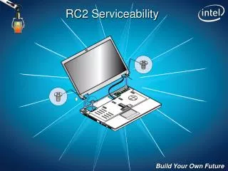

RC2 Serviceability
E N D
Presentation Transcript
Before servicing, always remove A/C power from the unit and disconnect the battery. Reduce the risk of ESD damage by using appropriate precautions. Terminology – A,B,C,D of notebooks, Expansion Boards, features Keep track of your screws! Safety and Ground Rules
Turn off power and unplug A/C adapter from notebook Remove battery Keyboard
Keyboard Remove two screws that hold keyboard cover with Medium red screwdriver
4. Turn system over with lid closed, carefully pry on plastic at hinges with fingernails, plastic tool, or (last resort) flat screwdriver Keyboard
Open lid 180 degrees and lift up on hinge plastics. Lift up and toward LCD. Once it is starting to lift, you may use a flat screwdriver under keyboard cover to carefully pry up at plastic tabs. TIP: The cover hooks toward the keyboard, so lift away from keyboard until cover is removed. Keyboard
6. Lift up on the keyboard to reveal the ribbon cable. Use fingernail to lift up on the BLACK ribbon cable connector tab. This tab flips up like a hinge and the cable should easily pull out. Keyboard is now removed. Keyboard TIP: Do not pull the latch tab out! It is difficult to reinstall.
Remove the rubber plugs that cover the six screws on the B-Plate with your fingers. Set them aside for reuse. Remove the 6 screws with #1 Phillips (tall red) screw driver. A-Plate
A-Plate Starting at the hinge area, pry the A-plate from the B-plate with your fingernails or plastic pry tool, working your way around the panel until the A-plate comes off.
You can now see how the A-plate, LCD, inverter, wireless antennas, and camera module can be serviced LCD
Close lid and remove D-door 5 short 2.5x3mm screws 2 long 2.5x6mm screws CPU CPU
Unhook WLAN antennas from wireless card Easy to access RAM, WLAN card, HDD and CPU Remove 2 long 2.5x6mm LCD screws LCD
Stand notebook up on side, gently pull wireless cables through, away from board. Pull up on tab to unplug adhesive backed LVDS Cable Place notebook back down and unscrew 4 hinge screws Remove LCD
Remove 1 ODD Screw Slide optical disk drive out ODD
Flip notebook, use fingernail to pull brown lock towards you, pull touchpad cable out. Repeat for fingerprint cable if installed. Remove 1 long 2.5x6mm screw under keyboard Start from hinge and pry C panel off
D-Tray Basics EXP-A Bluetooth EXP-B Speakers
D-Tray Basics Mobile Board I/O Bezel
Ensure all cables are clear and routed toward D-door Mate C-panel to D-tray Replace long 2.5x6mm screw under keyboard Insert touchpad cable, slide lock into place Repeat for fingerprint cable if installed (not shown) Reassemble
Slide optical disk drive out Install 1 long ODD Screw ODD TIP: Hold C-panel behind ODD screw if it does not thread correctly.
Line up the LCD onto C panel, place cables in front of hinges Flip back over to front, replace 4 hinge screws (short, black) Flip over and replace 2 LCD screws (long 2.5x6mm, black)
Plug in LVDS cable on left Thread WLAN cables Through tunnel (bend as needed) Over metal tab shown with arrow. (NOT as pictured) Out the bottom (stand notebook up on it’s side) Flip to bottom Reconnect wireless LAN cables to card, loop and tape if necessary TIP: Make sure cable is flat here near hinge and not obstructing tab behind it. Keyboard cover will not fit correctly and tab may break.
Make sure LCD cables are routed correctly Make sure screw holes are clear of wires
Replace D door 5 short 2.5x3mm screws 2 long 2.5x6mm screws CPU CPU
Open Notebook Plug in keyboard cable Push black hinge down to lock Replace keyboard cover, top first, click into place Keyboard
Ensure LVDS and WLAN cables are flat near hinge Replace A panel, snap all tabs in, you may need to support metal battery cover when you do this Replace 2 under battery screws (short with large flat head 2x1.6mm, black) Replace 2 LCD screws (long, 2.5x6mm) LCD
Follow the instructions to remove LCD until the LCD assembly is separated from the C tray (refer to slide 11 through step 9) Unplug touchpad and fingerprint (option) cable by pulling the dark portion of the connector 1-2 mm away from the light portion – Do not pull too far or the tabs will break! Turn the system over (upside down) Remove the screw marked ‘ODD’ and pull the drive out Remove the screws marked ‘HDD’, pull the cover off, and pull the black tab to remove the hard disk drive Remove the remaining screws marked ‘MB’ (All screws should be removed from the back side now) Unplug the three cables inside the D-door (speaker, BT, and Exp B) Turn the system over Remove one screw holding C tray to D tray still (pic) The C-tray should lift off the D-tray now Remove the one screw holding the MB to Expansion Board-A The MB should lift off the EB-A connector Remove the cable from EB-A (docking SKUs only) Remove the I/O panel from the MB Mobile Board
Remove thermal module screws in reverse order (…3,2,1) On some models, the screws will remain in the module Use a flat-head screwdriver to rotate the CPU lock mechanism 180 degrees to the unlock position Carefully lift up on the CPU, which should easily remove if previous step was performed correctly Ensure thermal pads are on the thermal module for the CPU and other system chips – replace as necessary CPU
Use your fingernails to pull the metal retention tabs away from each other Lift up on the first module and pull up and out of the socket Repeat steps 1-2 for remaining module Memory
Remove any antennas or other cabling that may be attached to your minicard (follow manufactures instructions) If cards are held with screws, remove them and any brackets that may be in place If cards are snapped in to a retainer, squeeze the retainer with your fingernails to release the card Lift up on the front edge of the card and gently pull it out MiniCards