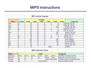
Lecture 8. MIPS Instructions #2 – Memory Access (Load/Store) Instructions
230 likes | 855 Views
2010 R&E Computer System Education & Research. Lecture 8. MIPS Instructions #2 – Memory Access (Load/Store) Instructions. Prof. Taeweon Suh Computer Science Education Korea University. Why Should CPU Access Memory?. Memory (DDR).

Lecture 8. MIPS Instructions #2 – Memory Access (Load/Store) Instructions
E N D
Presentation Transcript
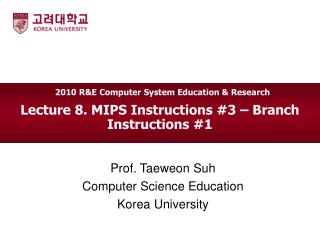
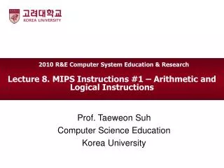
2010 R&E Computer System Education & Research Lecture 8. MIPS Instructions #2 – Memory Access (Load/Store) Instructions Prof. Taeweon Suh Computer Science Education Korea University
Why Should CPU Access Memory? Memory (DDR) • Initially, everything (your code and data) is stored in main memory • CPU should access (read/write) main memory to execute your program • So, 2 purposes • Instruction read: CPU reads instructions from memory • Data read/write: CPU reads data from memory and writes data to memory Hello World Binary (machine code) CPU 01101000 01100000 00110011 11100101 01101000 01100000 00110011 11100101 11100111 00110000 01010101 11000011 10100000 00011111 11100111 00011110 11110011 11000011 00110011 01010101 Address Bus 11100111 00110000 01010101 11000011 CPU Main Memory (DDR) 10100000 00011111 11100111 00011110 11110011 11000011 00110011 01010101 C compiler (machine code) FSB (Front-Side Bus) North Bridge Data Bus “Hello World” Source code in C DMI (Direct Media I/F) South Bridge
Instruction Access (Read) • How does CPU access (read) instructions from main memory? • MIPS has a 32-bit register called PC (program counter) inside the CPU • PC is initialized with a predefined address at reset • Then, PC gets changed as each instruction is executed • Every CPU has a register that keeps track of the current instruction address in execution • Many CPUs use the same term (PC) • One exception is x86, where the term IP (instruction pointer) is used to track the current instruction address.
Instruction Access & Execution Illustration Memory Address Bus 0x0020 0x001C 0x0018 0x0014 0x0010 0x000C 0x0008 0x0004 0x0000 CPU add v0,3 sw v0,8(s8) li v0,9 sw v0,4(s8) lw v1,8(s8) lw v0,4(s8) nop addu v0,v1,v0 sw v0,0(s8) PC Data Bus 0x0000 0x0008 0x0004 0x0008 0x0004 0x0000 nop addu v0,v1,v0 sw v0,0(s8) Byte address
Data Read/Write • As mentioned, everything (your code and data) is stored in main memory • You define data to be used in your code • Example: int a, b, c; • You sometimes define complex data structures such as arrays and structs • Example: int dummy [100]; • These data can contain many more data elements than registers can accommodate in CPU • CPU keeps only a small amount of data in registers on the fly • Thus, MIPS (and all other CPUs) must provide instructions that transfer data between memory and registers • Such instructions are called data transfer instructions • To access data in memory, the instruction must supply the memoryaddress
Data Transfer Illustration CPU (MIPS) PC Address Bus 0x0000 0x0004 0x0008 0x0004 0x0008 0x0000 Registers 32 bits Memory $zero 0x00110011 0x00220022 0x00220022 0x00110011 0x0018 0x0014 0x0008 0x0004 0x0000 0x0018 0x0014 $at 0x00110011 Data Bus 0x00220022 $v0 + R3 $v1 0x00330033 add v0,v1,v0 add v0,v1,v0 lw v1, 8(s8) lw v0, 4(s8) … lw v1, 8(s8) lw v0, 4(s8) $fp $ra
Word • Wordis a term for the natural unit of data used by a particular computer design • A word is simply a fixed-sized group of bits that are handled together by the machine • The number of bits in a word is an important characteristic of a computer architecture • The size of a word is reflected in many aspects of a computer's structure and operation • The majority of the registers in the computer are usually word-sized • Modern computers usually have a word size of 32, or 64 bits • The word size of MIPS is 32 bits (4 Bytes)
Memory Address • Word-address • Byte-address Main Memory (64KB) Main Memory (64KB) …… …… 0x000C 0x0003 0x000C Word (4 Bytes) 0x000B Byte 0x000A Byte 0x0009 Byte 0x0008 0x0002 0x0008 Byte Word (4 Bytes) 0x0007 Byte 0x0006 Byte 0x0005 Byte 0x0004 0x0001 0x0004 Byte Word (4 Bytes) 0x0003 Byte 0x0002 Byte Byte 0x0001 0x0000 0x0000 Byte 0x0000 Byte address in hex Byte address in hex Word address in hex
MIPS Memory Access Instruction - lw • lw instruction reads a word (32-bit) from memory and loads into a register • Instruction format (I format) lw rt, address • Example: lw $t0, 24($s3) # load (read) word from memory # $t0 <= [$s3 + 24] opcode rs rt immediate 35 19 8 24 MIPS architect defines the opcode binary 100011 10011 00000 01000 00000 011000 100011 10011 01000 00000 00000 011000 hexadecimal 0x8E68 0018
0x120040af 0x120040ae $t0 0x120040ad 0x120040ac MIPS Memory Access Instruction – lw (Cont) lw $t0, 24($s3) #load (read) word from memory # $t0 <= [$s3 + 24] Assume that $s3 has 0x12004094 $s3 + 2410 = 0x1200 40ac 0x7fff ffff Main Memory (2GB) 0xAABBCCDD 0xAABBCCDD . . . 1010 1100 = 0x120040ac 0x12004094 $s3 0001 1000 // 24 = 0x18 + . . . 1001 0100 // $s3 = 0x12004094 0x120040ac Address Bus CPU 0x00000003 0x00000002 0x00000001 0x00000000 Byte address in hex Data Bus
MIPS Memory Access Instruction – lw (Cont) • Instruction format (I format) • The memory address (32 bit address) is formed by adding the contents of the base address register to the offset value • The immediate specified in an instruction is a 16-bit 2’s complement number in the range [-32768, 32767] opcode rs rt immediate Main Memory base + ? base base + ?
MIPS Memory Access Instruction - sw • sw instruction stores (writes) a word (32-bit) from register to main memory • Instruction format (I format) sw rt, address • Example: sw $t2, 8($s3) # store(write) word to memory # [$s3 + 8] <= $t2 opcode rs rt immediate 43 19 10 8 MIPS architect defines the opcode binary 101011 10011 00000 01010 00000 001000 101011 10011 01010 00000 00000 001000 hexadecimal 0xAE6A 0008
Test-run MIPS Assembler • Check out the class web for instructions on how to build MIPS cross-compiler on Linux • Test-generate binary from the MIPS assembly program with assembler add $t0, $s1, $s2 # $t0 <= $s1 + $s2 sub $t2, $s3, $s4 # $t2 <= $s3 - $s4 lw $t0, 24($s3) #load (read) word from memory # $t0 <= [$s3 + 24] sw $t2, 8($s3) # store(write) word to memory # [$s3 + 8] <= $t2 0x0232 4020 0x0274 5022 0x8E68 0018 0xAE6A 0008 Memory (DDR) Address Bus MIPS CPU 0x0232 4020 0x0274 5022 0x8E68 0018 0xAE6A 0008 Data Bus
Loading and Storing Bytes • Since bytes (8 bits) are so useful, most architectures provide capability of addressing and accessing individual bytes in memory • Alignment restriction - the memory address of a word must be on natural word boundaries (a multiple of 4 in MIPS-32) • Let’s go over byte-addressable instructions • lb, sb
MIPS Memory Access Instruction - lb • lb instruction reads a byte (8-bit) from memory and loads into a register • Instruction format (I format) lb rt, address • Example: lb $t0, 1($s3) # load (read) byte from memory # $t0 <= [$s3 + 1] opcode rs rt immediate 32 19 8 1 binary 100000 10011 00000 01000 00000 000001 100000 10011 01000 00000 00000 000001 hexadecimal 0x8268 0001
Where to Loaded and How? lb $t0, 1($s3) # load (read) byte from memory # $t0 <= [$s3 + 1] • Byte is loaded into the LSB (Least Significant Byte) of the register $t0 and sign-extended bit 31 32-bit (4 bytes) bit 0 register $t0 Sign-extended 1 Byte MSB LSB • If you don’t want to have it sign-extended, use the lbu (Load byte unsigned) instruction lbu $t0, 1($s3) # load (read) byte from memory # $t0 <= [$s3 + 1] opcode rs rt immediate 36 19 8 1
MIPS Memory Access Instruction - sb • sb instruction writes a byte (8-bit) to memory from a register • Instruction format (I format) sb rt, address • Example: sb $t0, -7($s3) # store (write) byte to memory # $t0 <= [$s3 + (-7)] opcode rs rt immediate 40 19 8 -7 binary 101000 10011 11111 01000 11111 111001 101000 10011 01000 11111 11111 111001 hexadecimal 0xA268 FFF9
Where to Stored and from Where? • sbtakes the byte from LSB of a register and write it to a byte in memory • It does not change the other bits in a word in memory (not sign-extension!)
Endianness • Byte addressable memories are organized in a big-endianor little-endian fashion • In both formats, • The most significant byte (MSB) is on the left • The least significant byte (LSB) is on the right • Endian • In big-endian machines, bytes are numbered starting with byte 0 at MSB • Examples: IBM 360/370, Motorola 68k, MIPS, Sparc, HP PA • In little-endian machines, bytes are numbered starting with byte 0 at LSB • Examples: Intel x86, DEC Vax, DEC Alpha (Windows NT) • The choice of Endianness is completely arbitrary, but leads to hassles when sharing data between big-endian and little-endian computers • Why so messy? • Blame early computer designers!!! byte 0 byte 1 byte 2 byte 3 big endian Word (4 bytes) MSB LSB byte 3 byte 2 byte 1 byte 0 little endian
Endianness Example • Suppose that $s0 initially contains 0x23456789. After running the following program on a big-endian machine, what value does $s0 contain? sw $s0, 0($0) # [0 + $0] <= $s0 lb $s0, 1($0) # $s0 <= [1 + $0] Memory Memory MSB MSB 0x23 0x23 0x45 0x45 0x67 0x67 0x89 0x89 LSB LSB byte 0 byte 1 byte 2 byte 3 Byte 3 byte 2 byte 1 byte 0 Little endian big endian • How about in a little-endian machine?
Confused? See this… • Suppose that $s0 initially contains 0x23456789 sw $s0, 0($0) # [0 + $0] <= $s0 • After sw instruction, Main Memory (64KB) …… 0x000C 0x000B Byte 0x000A Byte 0x0009 Byte 0x0008 Byte 0x0007 Byte 0x0006 Byte Little endian big endian 0x0005 Byte 0x0004 Byte 0x23 0x45 0x67 0x89 0x0003 Byte 0x89 0x67 0x45 0x23 0x0002 Byte Byte 0x0001 Byte 0x0000 Byte address in hex
How to load a 32-bit constant? • How to load a 32-bit constant into a register? • Use lw instruction • Use 2 instructions (lui, ori) • lui:"load upper immediate" instruction • ori:Then must get the lower order bits right • Example: lui $t0, 0x5678 ori $t0, $t0, 0x1234 $t0 0x5678 0000000000000000 0000000000000000 0x1234 $t0 0x5678 0x1234