Download
1 / 34
350 likes | 568 Views
Instrumentation Selection Strategies. Robert Nigbor nees@UCLA. OUTLINE. Some sources of instrumentation selection information Common types of measurements in NEES research Introduction to the Operating Range concept for sensor + data acquisition selection.

E N D
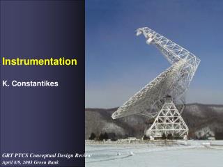
Instrumentation Selection Strategies Robert Nigbor nees@UCLA Instrumentation Symposium 10/9/2010 Nigbor
OUTLINE • Some sources of instrumentation selection information • Common types of measurements in NEES research • Introduction to the Operating Range concept for sensor + data acquisition selection Instrumentation Symposium 10/9/2010 Nigbor
Training & Information on Instrumentation Selection • A question for the audience – how many universities have hands-on instrumentation courses as part of the CE curriculum? • Example: Prof. Muratore’s ME Instrumentation & Data Acquisition course at Rice • Professional Organizations • ASCE • IEEE • Vendors • IOTech • National Instruments Instrumentation Symposium 10/9/2010 Nigbor
www.mccdaq.com/handbook/handbook.aspx Instrumentation Symposium 10/9/2010 Nigbor
www.mccdaq.com/handbook/resource_center.aspx Instrumentation Symposium 10/9/2010 Nigbor
www.ni.com/academic/measurements_curriculum.htm Instrumentation Symposium 10/9/2010 Nigbor
Review of Basic Instrumentation Issues Instrumentation Symposium 10/9/2010 Nigbor
Basic Instrumentation Blocks Graphics from www.ni.com DAQ Fundamentals Instrumentation Symposium 10/9/2010 Nigbor
Typical Analog-to-Digital Instrumentation System Signal Conditioner Excitation Sensor Volts Amplification Low Pass Filter Bridge Completion Microvolts to Volts depending on the sensor Recording, Storage and Display Sample and Hold Analog To Digital Converter Multiplexing and data transmission Bits Data Acquisition Unit From John F. Muratore’s course Instrumentation Symposium 10/9/2010 Nigbor
What it really looks like! Instrumentation Symposium 10/9/2010 Nigbor
NEES Experiments typically use tens or hundreds of sensor channels, compared to hundreds or thousands in Aerospace, Mechanical, Physics, and Geophysics applications. Instrumentation Symposium 10/9/2010 Nigbor
The Most Common NEES Measurements: Position, Motion, Strain, Force, Pressure • Linear Position • Angular Position • Linear Velocity • Angular Velocity/Rate • Acceleration • Strain in steel & concrete • Force via Strain • Pressure via strain Instrumentation Symposium 10/9/2010 Nigbor
From John F. Muratore’s course Instrumentation Symposium 10/9/2010 Nigbor
String Potentiometer From www.spaceagecontrol.com Instrumentation Symposium 10/9/2010 Nigbor
Linear Variable Differential Transformer (LVDT) Typically core is attached by a shaft to the object whose position is being measured LVDT core centered – no signal Core right – magnitude is a function of position in opposite phase as Ein Core left – magnitude is a function of position in same phase as Ein Instrumentation Symposium 10/9/2010 Nigbor
Accelerometer • Types of Accelerometers: • Electronic : transducers produce voltage output • Servo controlled: use suspended mass with displacement transducer • Piezoelectric: Mass attached to a piezoelectric material, which develops electric charge on surface. Principle: An acceleration a will cause the mass to be displaced by ma/k or alternatively, if we observe a displacement of x, we know that the mass has undergone an acceleration of kx/m. Generally accelerometers are placed in three orthogonal directions to measure accelerations in three directions at any time. Sometimes geophones (velocity transducers) are attached to accelerometers to measure the seismic wave velocities. CEE125, Spr10, Lecture 4
Earthquake Sensors – Accelerometer Example: Kinemetrics EpiSensor CEE125, Spr10, Lecture 4
Strain Gage As the material to which the gage is bonded increases in length (tension), the cross sectional area of the wire in the strain gage decreases. As area decreases, the resistance increases because resistance is inversely proportional to wire cross sectional area Instrumentation Symposium 10/9/2010 Nigbor
Typical Implementation via Bridge Circuit: Change in Resistance Change in Voltage Instrumentation Symposium 10/9/2010 Nigbor
Load Cells – Linear Force • Strain gage bridge measures elastic strain in material due to applied force Instrumentation Symposium 10/9/2010 Nigbor
Basic Pressure Sensor Types Capacitance Pressure Transducer Piezoelectric Pressure Transducer Strain gage pressure transducer From John F. Muratore’s course Instrumentation Symposium 10/9/2010 Nigbor
Measurement Needs and Constraints • Instrumentation design must consider amplitude, time, and frequency needs and constraints • ALL measurement systems have limitations in all three domains • A large part of the ART of instrumentation design and implementation is the optimization of needs and constraints Instrumentation Symposium 10/9/2010 Nigbor
Example: Static versus Dynamic Displacements LVDT’s here work for slow (quasi-static) motions but not for vibrations/dynamic motions, due to resonance of sensor and frame Instrumentation Symposium 10/9/2010 Nigbor
Example: Piezoelectric Accelerometers & Earthquake Motions Not Sensitive to <1Hz Motions, an important part of earthquake shaking Instrumentation Symposium 10/9/2010 Nigbor
“Operating Range” • Tool for considering both amplitude & frequency ranges in an instrumentation system • Tool for comparing instrumentation operating range with measurement need • Time must be considered separately, but this is often a data acquisition issue instead of a sensor issue Instrumentation Symposium 10/9/2010 Nigbor
Operating Range Diagram Maximum or Clip Level Operating Range of Component or System Amplitude, usually in narrow band like 1/3-octave Resolution or Noise Level Lower Corner Frequency Upper Corner Instrumentation Symposium 10/9/2010 Nigbor
Operating Range Diagram Maximum or Clip Level Operating Range of Component or System Phenomenon 1: Within Operating Range, is OK Amplitude, usually in narrow band like 1/3-octave Resolution or Noise Level Lower Corner Frequency Upper Corner Instrumentation Symposium 10/9/2010 Nigbor
Operating Range Diagram Maximum or Clip Level Phenomenon 2: Outside Operating Range, not OK Operating Range of Component or System Amplitude, usually in narrow band like 1/3-octave Resolution or Noise Level Lower Corner Frequency Upper Corner Instrumentation Symposium 10/9/2010 Nigbor
Instrumentation Selection Strategy • Understand amplitude, time & frequency limitations/constraints of potential instrumentation components and systems (sensor + signal conditioning + digitizer). • Compare with amplitude, time & frequency needs of your particular measurement challenge. • Make sure your particular phenomenon lies within the operating range of the instrumentation • The Operating Range Diagram is a useful tool for this comparison Instrumentation Symposium 10/9/2010 Nigbor