Download
1 / 17
180 likes | 298 Views
The PHENIX Experiment at the Relativistic Heavy Ion Collider (RHIC) aims to study quark-gluon plasma (QGP) and the spin structure of nucleons through particle collisions. The Time Expansion Chamber (TEC) plays a crucial role, measuring charged particle energy loss and tracking their momentum across a wide range of energies. With advanced subsystem capabilities, including a significant recording of Au-Au and proton-proton collision events, the TEC enhances our understanding of the dynamic processes within these high-energy interactions. Key design features enable precise measurements and contribute to groundbreaking nuclear research.

E N D
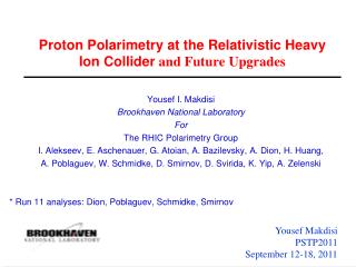
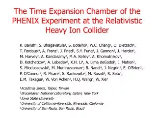
The Time Expansion Chamber of the PHENIX Experiment at the Relativistic Heavy Ion Collider K. Barish4, S. Bhagavatula3, S. Botelho5, W.C. Chang1, O. Dietzsch5, T. Ferdousi4, A. Franz2, J. Fried2, S.Y. Fung4, J. Gannon2, J. Harder2, M. Harvey2, A. Kandasamy2, M.A. Kelley2, A. Khomutnikov2, D. Kotchetkov4, A. Lebedev3, X.H. Li4, A. Lima deGodoi5, J. Mahon2, S. Mioduszewski2, M. Muniruzzaman4, B. Nandi4, J. Negrin2, E. O’Brien2, P. O’Connor2, R. Pisani2, S. Rankowitz2, M. Rosati3, R. Seto4, E.M. Takagui5, W. Von Achen2, H.Q. Wang4, W. Xie4 1Acadimia Sinica, Taipei, Taiwan 2Brookhaven National Laboratory, Upton, New York 3Iowa State University 4University of California-Riverside, Riverside, California 5University of San Paulo, San Paulo, Brazil
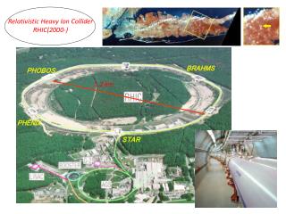
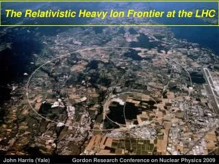
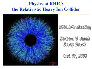
The Relativistic Heavy Ion Collider (RHIC) Project objectives: To detect and study a new state of matter, quark- gluon plasma (QGP) from Au-Au collisions: in 2000 at C.M. energy of 130 GeV; in 2001 at C.M. energy of 200 GeV (design); To understand the spin structure of the nucleon from proton-proton collisions: in 2001 at C.M. energy of 200 GeV. N S
Pioneering High Energy Nuclear Interaction eXperiment (PHENIX) To study signatures of QGP through kinematical and dynamic properties of electrons, muons, hadrons, and photons coming out of the collision point. Array of 11 subsystems for unbiased research. 2000: 4 million Au-Au minimum bias (all impact parameters) events recorded; 2001: 170 million Au-Au minimum bias events recorded (with 92 million minimum bias and 14 million rare events available for analysis) and 190 million p-p events. W The Time Expansion Chamber S N E
Passage of a Track through the PHENIX East Central Arm 400 Beam Line Ring Imaging Cherenkov Detector Electromagnetic Calorimeter Drift Chamber Time Expansion Chamber Pad Chamber 3 Time of Flight Multiplicity Vertex Detector Pad Chamber 1 5 cm 205 cm 245 cm 260 cm 410 cm East 480 cm Distances are closest to the vertex, not scaled 500 cm 510 cm
Functions of the Time Expansion Chamber (TEC) in the PHENIX TEC A) Measures charged particle ionization energy losses (dE/dx): Separation of electrons from pions: 1) over a momentum range 0.25 -3 GeV (e/p is 5% at 500 MeV), 2) after upgraded to the Transition Radiation Detector (TRD), over a momentum range 0.25-50 GeV via transition X-radiation detection (e/p is 1.5% at 500 MeV). B) Tracks all charged particles and produces direction vectors that match tracking information from the Drift and Pad Chambers to complete track determination in the PHENIX. Single point track resolution of 250 mm and two track separation of 2 mm. C) Measuring the transverse momentum of a charged particle. PHENIX East Central Arm
Geometry of the TEC 2000 2001
1) Arranged in 6-plane 4 sectors (in 2000 and 2001 only 4 planes were instrumented electronically). 2) Covers 900 of the PHENIX azimuthal angle f and 0.35 units of pseudorapidity h (approximately 400 of the polar angle q ). 3) Distance from the collision vertex approximately R = 410-457 cm. 4) 64,080 wires and 20,480 readout channels. Design Parameters of the TEC 5) Filled with Ar-CH4 (P-10) gas (90% of argon and 10% of methane) with the effective gas gain of 10000 (in 2000 and 2001 the effective gas gain was 2000-5000). (Gain is the number of electrons produced in a signal wire by one electron knocked out by a charged track). 6) Dimensions of the planes: 3.00 m x 1.69 m for the smallest and 3.49 x 1.90 m for the largest. 7) 320 Front-End Modules (FEM) and 640 Preamplifier/Shaper Boards (PS) (in 2001 216 FEMs and 432 PS Boards). TEC six-plane sector
Mechanical Design of the Plane cathode (Au-Cu-Be) anode (Au-W-Re) charged particle 4 mm 8 mm Drift velocity 15-50 mm/ms 6 mm Filled with Ar-CH4 (P-10) gas East 30 mm Electric field Cu-Mylar windows 68 mm To be filled with TRD fiber radiator beam direction
Electronics chain dE/dx Gain x25 From anode 95 ns preamplifier Tail cancellation Gain x5 TR 32 channel Preamp/Shaper board Flash Analog- Digital Converter Digital Memory Unit Data Delay and Buffering Data Formatter PHENIX format To PHENIX Data Collection Module FPGA Data format ArcNET Board configuration Digital parameters 64 channel Front-End Module Timing and mode bits Communication
Signal sampling Gain x5 TR 3 bits 3 level ADC (TR) 5 bits Encoder Analog voltage 28 bits 28 level ADC (dE/dx) To Digital Memory Unit Gain x25 dE/dx FADC dE/dx signal: 0.2-0.3 keV (MIP in Xe) TR signal: 3-10 keV (X-rays in Xe) Timing distributions for reconstructed charged particles
Track reconstruction y inclination angle beam direction a charged particle Hit pairs on the same track have the same a and f. A peak in the a-f space indicates the track. TEC f azimuthal angle x (East) Transverse momentum as a function of a: pt = 1/(21.5*a). reference circle R = 450 cm In 2000 the transverse momentum resolution is 4.8%+5.5%*pt *Studied by A.Lebedev, S. Bhagavatula, and M. Rosati
Relative space resolution in 2000 Average resolution of the TEC track in respect to associated hits in other PHENIX subsystems: Distance between the TEC track and associated hit in the EMC
Transverse momentum spectra in 2000 Transverse momentum spectra of charged hadrons obtained exclusively from TEC tracks match with the results from the PHENIX Drift Chamber tracks. Arbitrary units Black: Drift Chamber Blue and Red: Time Expansion Chamber *Studied by A.Lebedev, S. Bhagavatula, and M. Rosati
Identification of charged hadrons in 2000 • Capable of effective hadron • identification through m2 • measurements using Time of • Flight hodoscope data. Can • clear separate : • pions from kaons with • transversemomenta up • to 1.2 GeV; • 2) kaons fromprotons with • transverse momenta up • to 1.4 GeV. pions kaons protons Mass2 distribution of the charged particles in TEC for pt = 1.0 – 1.2 GeV
dE/dx Study in 2000 kaons pions Estimated gas gain ~3000 protons electrons Identify hadrons and electrons with the Drift Chamber, Ring Imaging Cherenkov Detector and the Time of Flight hodoscope protons Then look at identified species in the TEC dE/dx vs. momentum distribution kaons electrons pions *Studied by X.H. Li
dE/dx Study in 2001 *Studied by X.H. Li Estimated gas gain ~5000
Future • Upgrade into the Transition Radiation Detector (capable of pion/electron separation for momenta beyond 50 GeV) by: a) electronically instrumenting from 4 to 6 planes, b) installing polypropelene fiber radiators in front of each wire plane, c) use xenon-helium-methane (Xe-He-CH4) gas mixture. (To be done by October 2002.) 2) Possible construction of the TEC in the PHENIX West Central Arm (2004/2005).