Download
1 / 100
1.04k likes | 1.23k Views
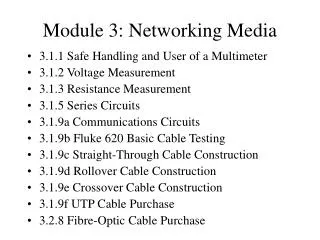
Mod 3 – Networking Media. Objectives Ziele. Discuss the electrical properties of matter. Define voltage, resistance, impedance, current, and circuits. Describe the specifications and performances of different types of cable.

E N D
Objectives Ziele • Discuss the electrical properties of matter. • Define voltage, resistance, impedance, current, and circuits. • Describe the specifications and performances of different types of cable. • Describe coaxial cable and its advantages and disadvantages over other types of cable. • Describe shielded twisted-pair (STP) cable and its uses. • Describe unshielded twisted-pair cable (UTP) and its uses. • Discuss the characteristics of straight-through, crossover, and rollover cables and where each is used. • Explain the basics of fiber-optic cable. • Describe how fibers can guide light for long distances. • Describe multimode and single-mode fiber. • Describe how fiber is installed. • Describe the type of connectors and equipment used with fiber-optic cable. • Explain how fiber is tested to ensure that it will function properly. • Discuss safety issues dealing with fiber-optics.
Basic of Electricity • Discuss the electrical properties of matter. • Define voltage, resistance, impedance, current, and circuits.
Atoms and electrons • Electrons – Particles with a negative charge that orbit the nucleus • Nucleus – The center part of the atom, composed of protons and neutrons • Protons – Particles with a positive charge • Neutrons – Particles with no charge (neutral) • Electrons stay in orbit, even though the protons attract the electrons. • The electrons have just enough velocity to keep orbiting and not be pulled into the nucleus, just like the moon around the Earth.
Atoms and electrons • Loosened electrons that stay in one place, without moving, and with a negative charge, are called static electricity. • If these static electrons have an opportunity to jump to a conductor, this can lead to electrostatic discharge (ESD). • ESD, though usually harmless to people, can create serious problems for sensitive electronic equipment. • The basis for all electronic devices is the knowledge of how insulators, conductors and semiconductors control the flow of electrons and work together in various combinations.
Voltage (force or speed) • Because electrons and protons have opposite charges, they are attracted to each other. • Similar to north and south poles of two magnets • When charges are separated, causes a force or pressure field between the charges. • This force is voltage. • Voltage can be considered as, the speed of the electron traffic.
Voltage (force or speed) • This process occurs in a battery, where chemical action causes electrons to be freed from the negative terminal of the battery. • The electrons then travel to the opposite, or positive, terminal through an EXTERNAL circuit. • The electrons do not travel through the battery itself. • Remember that the flow of electricity is really the flow of electrons.
Voltage (force or speed) • Direct-current (DC) voltage • Example: battery • Te movement of electrons in a DC circuit is always in the same direction, from negative to positive. • Alternating-current (AC) voltage • The positive and negative terminals of the AC voltage source regulary change to negative and positive and back again. • The change makes the direction of electron movement change, or anternate with respect to time. • Alternating current is the more common type of electricity as permanent supply to commercial and industrial buildings and domestic premises.. DC AC
Voltage - AC • This is a graphical representation of alternating current called a sine wave. Note the two axes. • The vertical axis represents the direction and magnitude of the current; the horizontal axis represents time. • When the wave form is above the time axis, current is flowing in what is called the positive (+) direction. • When the wave for is below the time axis, the current is flowing in the opposite, or what is called the negative (-) direction. • In period 1, current starts at zero magnitude, increases to a maximum magnitude, and diminishes back to zero. • In period 2 shown in current flow reverses direction and immediately begins to increase in the negative direction. • When current flow reaches maximum magnitude, it diminishes until it reaches zero again. • The pattern of alternating current flowing first in the positive direction (period 1) and then in the negative direction (period 2), is called one cycle (periods 1 + 2). http://www.gelighting.com/eu/institute/firstlight/module01/07.html
Current (Amperage) • The action of electricity flowing in a conductor is called "current flow". • Current is the flow of charges that is created when electrons move. • When voltage, electrical pressure, is applied and a path for the current exists, electrons move from the negative terminal to the positive terminal. • The symbol for current is the capital letter “I". • Measured in amperes, or amp, "A" • Amp = Number of charges per second that pass by a point along a path. • The amount of electron traffic. • More electron traffic that is flowing through a circuit, the higher the current. • DC current is one direction, AC current is two directions. • You can compare water flow to electron flow. • A flow meter can be used to measure the quantity of water flowing in a pipe, measured in litres per second. • An ampmeter can be used to measure current flow through a conductor.
Wattage • If current (amperage) is the amount or volume of electron traffic that is flow, … • Then voltage can be thought of as the speed of electron traffic. • Current (amps) times Voltage = Wattage (W) • W = V x I • A watt (W) is the basic unit of electrical power. • Wattage is how much power electrical devices consume or produce. • Static electricity has very high voltage (jumping a gap of over an inch), but very low amperage, which means can create a shock, but no injury. • A starter motor relatively low 12 volts, but requires high enough amperage to turn over the engine. • Lightening, has both high voltage and high amperage, an can cause severe injury or damage.
Resistance (DC) and Impedance (AC) • The materials through which current flows offer varying amounts of opposition, or resistance to the movement of the electrons. • The materials that offer very little, or no, resistance, are called conductors. • Those materials that do not allow the current to flow, or severely restrict its flow, are called insulators. • Semiconductors are materials where the amount of electricity they conduct can be precisely controlled. • The amount of resistance depends on the chemical composition of the materials.
Resistance (DC) and Impedance (AC) • Resistance(R) is the property of material that resists electron movement. • Generally refers to DC circuits • Conductors - low resistance • Insulators - high resistance • Impedance (Z) is the resistance to the movement of electrons in an AC circuit. • Ohm (, omega)– unit of measurement for resistance and impedance
Resistance (DC) and Impedance (AC) • All materials that conduct electricity have a measure of resistance to the flow of electrons through them. • These materials also have other effects called capacitance and inductance associated with the flow of electrons. • capacitance • A capacitor is a passive electronic component that stores energy in the form of an electrostatic field. • The number of electrons it can hold under a given electrical pressure (voltage) is called its capacitance or capacity. • inductance • An inductor is a passive electronic component that stores energy in the form of a magnetic field. • In its simplest form, an inductor consists of a wire loop or coil. • inductance is the property of a circuit by which energy is stored in the form of an electromagnetic field. • The three characteristics, resistance, capacitance, and inductance, comprise impedance, which is similar to and includes resistance.
Circuits • Current flows in closed loops called circuits. • These circuits must be composed ofconducting materials, and must have sources of voltage. • Voltage causes current to flow, while resistance and impedance oppose it. • Current consists of electrons flowing away from negative terminals and towards positive terminals. • Knowing these facts allows people to control a flow of current. • The relationship among voltage, resistance, and current is: • voltage (V) = current (I) multiplied by resistance (R). • Ohm’s law, V=I*R
Circuits • Electrons flow inclosed circuits, or complete loops. • The chemical processes in the battery cause charges to build up. • This provides a voltage, or electrical pressure, that enables electrons to flow through various devices. • The lines represent a conductor, which is usually copper wire. • Think of a switch as two ends of a single wire that can be opened or broken to prevent electrons from flowing. • When the two ends are closed, fixed, or shorted, electrons are allowed to flow. • Finally, a light bulb provides resistance to the flow of electrons, causing the electrons to release energy in the form of light. • The circuits involved in networking use a much more complex version of this very simple circuit.
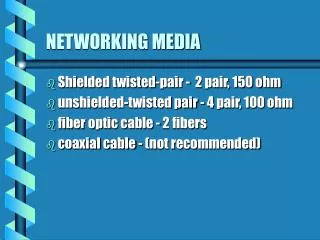
Copper Media • Describe the specifications and performances of different types of cable. • Describe coaxial cable and its advantages and disadvantages over other types of cable. • Describe shielded twisted-pair (STP) cable and its uses. • Describe unshielded twisted-pair cable (UTP) and its uses. • Discuss the characteristics of straight-through, crossover, and rollover cables and where each is used.
Cable Specifications • Cables have different specifications and expectations pertaining to performance.
Cable Specifications • Cables have different specifications and expectations pertaining to performance: • What speeds for data transmission can be achieved using a particular type of cable? The speed of bit transmission through the cable is extremely important. The speed of transmission is affected by the kind of conduit used. • What kind of transmission is being considered? Will the transmissions be digital or will they be analog-based? Digital or baseband transmission and analog-based or broadband transmission are the two choices. • How far can a signal travel through a particular type of cable before attenuation of that signal becomes a concern? In other words, will the signal become so degraded that the recipient device might not be able to accurately receive and interpret the signal by the time the signal reaches that device? The distance the signal travels through the cable directly affects attenuation of the signal. Degradation of the signal is directly related to the distance the signal travels and the type of cable used.
Cable Specifications • 10BASE-T • speed of transmission at 10 Mbps • type of transmission is baseband, or digitally interpreted • T stands for twisted pair
Cable Specifications • 10BASE5 • speed of transmission at 10 Mbps • type of transmission is baseband • 5 represents the capability of the cable to allow the signal to travel for approximately 500 meters before attenuation could disrupt the ability of the receiver to appropriately interpret the signal being received. • often referred to as Thicknet
Cable Specifications • 10BASE2 • speed of transmission at 10 Mbps • type of transmission is baseband • The 2, in 10BASE2, represents the capability of the cable to allow the signal to travel for approximately 200 meters, before attenuation could disrupt the ability of the receiver to appropriately interpret the signal being received. 10BASE2 is often referred to as Thinnet.
Coaxial Cable • Woven copper braid or metallic foil • Acts as the second wire in the circuit • Acts as a shield for the inner conductor. • Reduces the amount of outside electro-magnetic interference. • Comprises half the electric circuit • Special care must be taken to ensure a solid electrical connection a both ends resulting in proper grounding • Poor shield connection is one of the biggest sources of connection problems in the installation of coaxial cable.
Coaxial Cable • Advantages: • Requires fewer repeaters than twisted pair • Less expensive than fiber • It has been used for many years for many types of data communication, including cable television • Disadvantages: • More expensive and more difficult to install than twisted pair • Needs more room in wiring ducts than twisted pair
Shielded Twisted Pair (STP and ScTP) STP – Shielded Twisted Pair ScTP – Screened Twisted Pair • Shielded twisted-pair cable (STP) combines the techniques of shielding, cancellation, and twisting of wires. • Each pair of wires is wrapped in metallic foil. • The four pairs of wires are wrapped in an overall metallic braid or foil. • A new hybrid of UTP with traditional STP is Screened UTP (ScTP), also known as Foil Twisted Pair (FTP). • ScTP is essentially UTP wrapped in a metallic foil shield, or screen.
Shielded Twisted Pair (STP and ScTP) • Greater protection from all types of external and internal interference than UTP. • Reduces electrical noise within the cable such as pair to pair coupling and crosstalk. • Reduces electronic noise from outside the cable, for example electromagnetic interference (EMI) and radio frequency interference (RFI). • More expensive and difficult to install than UTP. • Needs to be grounded at both ends
Unshielded Twisted Pair (UTP) • Unshielded twisted-pair cable (UTP) is a four-pair wire medium used in a variety of networks. • TIA/EIA-568-A contains specifications governing cable performance. • RJ-45 connector • When communication occurs, the signal that is transmitted by the source needs to be understood by the destination. • The transmitted signal needs to be properly received by the circuit connection designed to receive signals. • The transmit pin of the source needs to ultimately connect to the receiving pin of the destination.
Unshielded Twisted Pair (UTP) Straight-through Cross-over Rollover www.cisco.com/warp/ public/701/14.html
UTP Straight-through Cable • The cable that connects from the switch port to the computer NIC port is called a straight-through cable. Hub or Switch Host or Router
UTP Straight-through Cable Hub or Switch Host or Router
UTP Cross-over Cable • The cable that connects from one switch port to another switch port is called a crossover cable.
UTP Rollover Cable • The cable that connects the RJ-45 adapter on the com port of the computer to the console port of the router or switch is called a rollover cable.
UTP Rollover Cable Router Console port Terminal or a PC with terminal emulation software Rollover cable Com1 or Com2 serial port
Lab Activities • Lab Exercise: Fluke 620 Basic Cable Testing • In this lab, the student will use a simple cable tester to verify whether a straight-through or crossover cable is good or bad. • Lab Exercise: Straight-Through Cable Construction • In this lab, the student will build a Category 5 or Category 5e (CAT 5 or 5e) unshielded twisted pair (UTP) Ethernet network patch cable or patch cord and test the cable for continuity and correct pinouts, the correct color of wire on the right pin. • Lab Exercise: Rollover Cable Construction • In this lab, the student will build a Category 5 or Category 5e (CAT 5 or 5e) unshielded twisted pair (UTP) console rollover cable and test the cable for continuity and correct pin-outs, the correct wire on the right pin. • Lab Exercise: Crossover Cable Construction • In this lab, the student will build a Category 5 or Category 5e (CAT 5 or 5e) unshielded twisted pair (UTP) Ethernet crossover cable to T568-B and T-568-A standards and test the cable for continuity and correct pin-outs, correct wire on the right pin. • Lab Exercise: UTP Cable Purchase • This lab will introduce the variety and prices of network cabling and components in the market. The student will gather pricing information for UTP patch cables and bulk cable.
Making a Cable We will have a lab on this later.