Download
1 / 64
640 likes | 701 Views
Learn about digital filter design procedures, specifications, and transformations using MATLAB and various prototypes such as Butterworth, Chebyshev, and Elliptic. Understand critical concepts like frequency response and impulse response mapping for effective filter design.

E N D
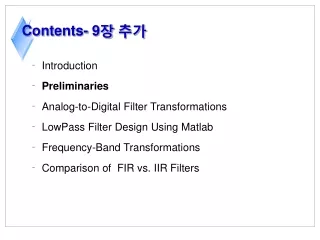
Contents- 9장 추가 • Introduction • Preliminaries • Analog-to-Digital Filter Transformations • LowPass Filter Design Using Matlab • Frequency-Band Transformations • Comparison of FIR vs. IIR Filters
Contents • Introduction(서론) • Preliminaries(예비 사항) - Absolute Specifications(절대 사양) - Relative Specifications(상대 사양) • Properties of Linear-Phase FIR Filters(선형 위상 필터의 특성) - Impulse Response(임펄스 응답) - Frequency Response(주파수 응답) - Zero Locations(영점 위치)
Introduction(서론) - 1 • 디지털 신호 처리의 두 가지 시스템 형태 - Digital Filter(디지털 필터): 시간 영역에서 신호 여과를 하는 시스템 - Spectrum Analyzer(스펙트럼 분석기 ): 주파수 영역에서 신호를 표현 하는 시스템 • Frequency Selective Type(주파수 선택적 형태) - FIR 필터와 IIR 필터는 대부분 주파수 선택적 형태를 갖음. - 주로 다대역(multi band), 저역통과(low pass), 고역통과(high pass) 대역통과(band pass) 필터들을 설계
Preliminaries - Absolute Specifications(절대 사양) - Relative Specifications(상대 사양)
Preliminaries(예비 사항 - 1) • 디지털 필터의 설계 단계 - Specification(사양): 필터를 설계하기 전에 몇 가지 사양을 가져야 함. ex) 정지대역의 끝: 50dB, 통과대역의 끝: 1dB - Approximation(근사): 사양 결정 후, 사양을 근사시키는 작업, 즉, 주어 진 사양을 필터 표현으로 구현.(차분방정식, 시스템 함수, 또는 임펄스 응답의 형태를 갖는 필터 표현) - Implementation(구현): 위 단계의 결과를 하드웨어나 컴퓨터 소프트웨 어로 구현
Preliminaries(예비 사항 - 3) • Absolute Specifications(절대 사양)과 Relative Specifications(상대 사양) - 은 이상적인 통과대역 응답에서 감수할 수 있는 허용오차(또는 리플) • 은 이상적인 정지대역 응답에서 감수할 수 있는 허용오차(또는 리플) (a) 절대 사양 • 는 dB로 나타낸 통과대역 리플 - 는 dB로 나타낸 정지대역 감쇠 (b) 상대 사양
Preliminaries(예비 사항 - 4) • 통과대역 리플 , 정지대역 리플 • 예제 7.1 - 어떤 필터의 사양에서 통과대역 리플은 0.25dB이고, 정지대역 감쇠는 50dB일때 , 을 구하라. Sol) 즉, 절대 사양을 알 때, 상대 사양에서의 허용오차를 구하라. 이므로,
Preliminaries(예비 사항 - 5) 또한, 이므로 • 예제 7.2 - 통과대역 허용오차 =0.01, 정지대역 허용오차는 =0.001이 주어질 때, 통과 대역 리플 와 저지대역 감쇠 를 구하라. Sol) 즉, 절대 사양을 알 때, 상대 사양에서의 허용오차를 구하라.
Impulse Invariance Transformation • We sample at some sampling interval to obtain • Sampling Operation : the analog and digital frequencies are related by or • Since on the unit circle and (analog frequency) on the imaginary axis, we have the following transformation from the s-plane to the z-plane: • The system function and are related through the frequency-domain aliasing formula
Design Procedure 1. Given digital frequency, choose and determine the analog frequencies 2. Design an analog filter using the specifications and 3. Using partial fraction expansion, expand into 4. Transform analog poles into digital poles to obtain the digital filter
Example 1 Transform Into a digital filter using the impulse invariance technique in which =0.1 (Solution) We first expand using partial fraction expansion : The poles are at and . Then from (8.25) and using =0.1, we obtain
Example 2 Demonstrate the use of the imp_invr function on the system function from Example 1 (Solution) b = 1.0000 -0.8966 a = 1.0000 -1.5595 0.6065
Example 3 Design a lowpass digital filter using a Butterworth prototype to satisfy (Solution)
The desired filter is a 6th-order butterworth filter whose system function is given in the parallel form
Example 4 Design a lowpass digital filter using a Chebyshev-I prototype to satisfy (Solution)
The desired filter is a 4th-order Chebyshev-I filter whose system function is
Example 5 Design a lowpass digital filter using a Chebyshev-II prototype to satisfy (Solution)
Example 6 Design a lowpass digital filter using an elliptic prototype to satisfy (Solution)
Bilinear Transformation • This mapping is the best transformation method; it involves a well-known function given by • Another name for this transformation is the linear fractional transformation because when cleared of fractions, we obtain • Which is linear in each variable if the other is fixed, or bilinear in s and z.
Substituting in (8.27), we obtain since the magnitude is 1. Solving for digital frequency as a function of analog frequency , we obtain This shows that is nonlinearly related to (or warped into) but that there is no aliasing. Hence in (8.28) we will say that is prewarped into
Example 6 Transform into a digital filter using the bilinear transformation. Choose =1 (Solution) Using (8.26), we obtain Simplifying,
Example 7 Transform the system function in Example 1 using the bilinear function (Solution)
Design Procedure 1. Choose a value for . This is arbitrary, and we may set 2. Prewarp the cutoff frequencies and ; that is, calculate and using (8.28) : 3. Design an analog filter to meet the specification and . We have already described how to do this in the previous section. 4. Finally, set and simplify to obtain as a rational function in
Example 8 Design the digital Butterworth filter of Example 3. The specifications are (Solution)
Example 9 Design the digital Chebyshev-I filter of Example 4. The specifications are (Solution)
Example 10 Design the digital Chebyshev-II filter of Example 5. The specifications are (Solution)
Example 11 Design the digital elliptic filter of Example 6. The specifications are (Solution)
1. [b, a] = butter(N, wn) 2. [b, a] = cheby1(N, Rp, wn) 3. [b, a] = cheby2(N, As, wn) 4. [b, a] = ellip(N, Rp, As, wn)
Example 12 Digital Butterworth lowpass filter design : (Solution)
Example 13 Digital Chebyshev-I lowpass filter design : (Solution)
Example14 Digital Chebyshev-II lowpass filter design : (Solution)
Example 15 Digital elliptic lowpass filter design : (Solution)
Comparison of Three Filters This comparison in terms of order N and the minimum stopband attenuations is shown in Table 8.1.
Lowpass Highpass Bandstop Bandpass • Typical specifications for most commonly used types of frequency-selective digital filters are shown below Figure 8.20 Specifications of frequency-selective filters
Let be the given prototype lowpass digital filter • Let be the desired frequency-selective digital filter • using two different frequency variables, and , with and , respectively. • Define a mapping of the form • Such that 1. G( ) must be a rational function in so that is implementable 2. The unit circle of the Z-plane must map onto the unit circle of the z-plane 3. For stable filters, the inside of the unit circle of the Z-plane must also map onto the inside of the unit circle of the z-plane
Let and be the frequency variables of Z and z • and on their respective unit circles • Then requirement 2 above implies that and or • The general form of the function G( ) that satisfies the above requirements is a rational function of the all-pass type given by • Where for stability and to satisfy requirement 3
Transformation Parameters Type of Transformation cutoff frequency of new filter Lowpass cutoff frequency of new filter Highpass lower cutoff frequency Bandpass upper cutoff frequency lower cutoff frequency Bandstop upper cutoff frequency
Example 16 In Example 13 we designed a Chebyshev-I lowpass filter with specifications and determined its system function Design a highpass filter with the above tolerances but with passband beginning at
(Solution) • From Table 8.2 Hence which is the desired filter