Flexible Use of Spectrum Rights for Enhanced Spectrum Management
This tutorial explores the concept of spectrum management, focusing on how the spectrum is allocated for communications and sensing purposes. Key topics covered include the physical properties of radio systems, the principles of command-and-control spectrum management, and the introduction of flexible-use rights. The tutorial addresses the processes by which spectrum users are selected, the types of rights associated with spectrum use, and the implications for future communication systems. Insights include the role of electrospace in signal management and the significance of various spatial, frequency, and temporal dimensions.

Flexible Use of Spectrum Rights for Enhanced Spectrum Management
E N D
Presentation Transcript
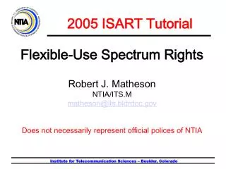
2005 ISART Tutorial Flexible-Use Spectrum Rights Robert J. Matheson NTIA/ITS.M matheson@its.bldrdoc.gov Does not necessarily represent official polices of NTIA Institute for Telecommunication Sciences – Boulder, Colorado
Spectrum Management • Spectrum management is the process of arranging the use of the spectrum for communications and sensing. • Who gets to use spectrum? • For what functions? • Under what restrictions? • What are the processes to decide? Institute for Telecommunication Sciences – Boulder, Colorado
Outline • 1. The Physical World /Engineering • Electrospace • Receivers • Interference • - - - 10-minute break - - - • 2. Spectrum Management • General comments • Command-and-control • 3. Flexible Use Rights • Pure electrospace rules (ideal receivers) • Modified electrospace rules (real receivers) • Extended rules for aggregation and division • Miscellaneous loose ends Institute for Telecommunication Sciences – Boulder, Colorado
Radio System Basics • Electrospace • Receivers Institute for Telecommunication Sciences – Boulder, Colorado
Radio System Basics - 1 • Radio systems have: • Transmitter (including transmitting ant) • Propagation path • Receiver (including receiving antenna) Communications – move data from transmitter to receiver. Sensing – Compare received signal with transmitted signal to study path (radars, sensors, etc.) Institute for Telecommunication Sciences – Boulder, Colorado
Radio System Basics - 2 • The Electrospace describes the appearance of radio signals: transmitters & propagation. • A receiver processes the electrospace to receive communications. • One major goal of frequency management is to arrange the signals in the electrospace so that the desired signal can be separated out by a simple and inexpensive receiver. Institute for Telecommunication Sciences – Boulder, Colorado
The Electrospace • Electrospace (described by Hinchman in1969) is a 7-variable description of EM field strength (hyperspace). • Physical location – lat., long., altitude 3-dim • Frequency – MHz 1-dim • Time - µS, hours, or years 1-dim • Direction-of-arrival – azimuth, elevation 2-dim • Electrospace describes radio signals, as they appear from an ideal receiver at the physical location. Note: receiver includes receiving antennas. Institute for Telecommunication Sciences – Boulder, Colorado
SpatialDimensions Strong signal Weak Signal Directional antennas Any spatial region: microcell to BTA, modify with directional antennas. Caution: some areas cannot be used well; coverage affected by terrain and buildings, height above ground. Match spatial to coverage. Institute for Telecommunication Sciences – Boulder, Colorado
Frequency Dimension • The frequency dimension is well behaved and intuitive, with a frequency band often divided up into many identical non-overlapping channels. Institute for Telecommunication Sciences – Boulder, Colorado
Time Dimension FCC recently mentioned “time” as one additional dimension that they would allow users to divide. Months – seasonal uses Hours – to broadcast special football game Hours – midnight-to-5am daily to send low cost computer updates. 10 ms TDMA timeslots every 50 ms. Useful for serving many intermittent activities. Institute for Telecommunication Sciences – Boulder, Colorado
Angle-of-Arrival Dimension 2. A receiver will see these 4 signals coming from directions of 4 arrows, which is angle-of-arrival for 4 xmtrs. T3 T2 3. A narrow beamwidth receiving antenna can select desired xmtr. T4 T1 R 1. Angle-of-arrival is different from coverage area. Consider coverage areas of 4 xmtrs. 4. Receiver antenna beamwidth counts, not transmitter beamwidth. Institute for Telecommunication Sciences – Boulder, Colorado
Angle of arrival - 2 Path 2 LOS path T R Path 3 Path 4 • Narrowbeam line-of-sight path (pt-pt microwave). 2. Multiple narrowbeam (NB) paths scattered from landscape. 3. NB receiver antenna isolates each path (difficult). 4. MIMO receiver forms multiple ortho- gonal vector sums to mathematically generate paths (easier). 5. Future application of generalized angle-of- arrival, using less- expensive techniques Institute for Telecommunication Sciences – Boulder, Colorado
The Electrospace • Electrospace is a 7-variable description of EM field strength (hyperspace). • Physical location – lat., long., altitude 3-dim • Frequency – MHz 1-dim • Time - µS, hours, or years 1-dim • Direction-of-arrival – azimuth, elevation 2-dim • . • A given “region” of electrospace is considered “occupied” if the field strength exceeds “X” W/MHz/m2. Institute for Telecommunication Sciences – Boulder, Colorado
Same spectrum, more users • The electrospace formalizes additional ways to divide up spectrum among more users. • Point-to-point microwave uses shaped pencil beam coverage areas and divides up angle-of-arrival. • Trunked radio systems adaptively divide time. • MIMO mathematically finds multiple paths by processing angle-of-arrival part of electrospace. • Advanced cognitive radios will be even better at dividing up the electrospace. Institute for Telecommunication Sciences – Boulder, Colorado
Radio Systems • Receivers and the electrospace create a radio system. • Receivers process the electrospace to give service (if successful) or interference (if not successful). • A sufficiently good receiver can separate any signals having different electrospace descriptions. Interference is caused only when a receiver is not “good-enough”. Might require adaptive antennas to null interference. • “Interference protection” really means“able to use a cheaper receiver.” Institute for Telecommunication Sciences – Boulder, Colorado
Interference - 1 Interference – any distortion of the processed desired signal caused by unwanted extraneous radio signals (excludes multipath, internal noise). Interference can be caused by co-channel operation, excessive sidebands, intermodulation in receiver, receiver overload, etc. Note: not by lack of signal. No sharp line between acceptable and unacceptable interference. All interference is unwanted. Even the possibility of interference is unwanted, since it requires more robust system design. Institute for Telecommunication Sciences – Boulder, Colorado
Interference - 2 • A faulty transmitter causes interference to other users – an “externalized cost” that the transmitter owner has no motivation to control. Therefore, regulations may be needed to control transmitters. • Externalized cost is either cost of interference, or cost of better receivers to prevent interference. Interference rules establish expected receiver capabilities. • A faulty receiver causes interference only to receiver user, who is well-motivated to fix receiver. No external controls are needed. Institute for Telecommunication Sciences – Boulder, Colorado
Interference – 3 Interference is always caused by an inadequate receiver and could be fixed by a “good-enough” receiver (though “good-enough” for some situations might require adaptive antennas to null out interference, or other very complex and expensive components). Using better receivers would decrease interference, and/or allow more signals to be transmitted before interference occurred. Therefore, using better receivers is always expected to improve spectrum efficiency. Institute for Telecommunication Sciences – Boulder, Colorado
Better Receivers “Better” receiver means anything that helps a receiver more successfully receive wanted signals. • Better IF filters to remove signals on adjacent channels • Better dynamic range to reduce IM and overload from strong signals • Better directional antennas to isolate desired signal from others • Better intelligence to adaptively re-tune to less crowded frequency • Better intelligence to change modulation and power • Etc. e.g., cognitive radios Institute for Telecommunication Sciences – Boulder, Colorado
Receiver standards? Using better receivers could improve spectrum efficiency. Therefore: Require minimum receiver performance standards? Yes, but … A major objective of good spectrum management is to develop rules that allow the use of cheap equipment (receivers), e.g. : Keep low power and high power bands separated, Use large duplex band structures, Limit maximum transmitter power, etc. Such features are intended to allow the use of cheaper receivers. “A major goal of spectrum management is to make the world safe for cheaper receivers.” Institute for Telecommunication Sciences – Boulder, Colorado
Receiver standards User groups who mutually depend on the performance of other members’ radios have good reasons to regulate minimum receiver performance of other members’ radios. Procurement of equipment often simplified by referring to receiver procurement standards. Receiver standards valuable to educate user about typical receiver performance requirements. None of above primarily concern spectrum management. Institute for Telecommunication Sciences – Boulder, Colorado
Receiver Summary • Receivers are a vital component of any radio system, greatly affecting performance of system. Receiver performance is an important part of system design. • All interference is caused when receiver performance is not sufficient for the given electrospace environment. Better receivers can improve spectrum efficiency, at a cost. Poor spectrum management rules may make it necessary to use better receivers. • The receiver user is usually well-motivated to get a “good-enough” receiver. Institute for Telecommunication Sciences – Boulder, Colorado
- - - 5-minute break - - - 5-minute break Next: Regulatory Concepts and flexible-use rules Institute for Telecommunication Sciences – Boulder, Colorado
Map of Spectrum Rights Specific Users (exclusive licenses) Traditional licenses (C&C) Auctioned bands Flexible-use rights Govt. Regulations Amateurs User Decisions Part 15 Spread spectrum Cordless phones, mesh networks (?) ISM bands General users (Commons) • Spectrum management represented on a 2-dimensional continuum. • Horizontal axis shows decision-making rights, from all-Govt to all-user. • Vertical axis shows how much a frequency is preferentially given to specific users versus general users. • Many areas of model are currently in widespread productive use. Institute for Telecommunication Sciences – Boulder, Colorado
Map of Spectrum Rights Specific Users (licenses) Traditional licenses (C&C) Auctioned bands Spectrum use rights Greater uncertainty Lower transmit power Govt. Regulations Amateurs User Decisions Part 15 Spread spectrum FRS, CB, Cordless phones ISM bands General users (Commons) People have often thought about radio licenses on an axis between upper-left and lower-right corners. Licensed systems with high-power transmitters (traditional C&C) Non-licensed systems with low-power transmitters (Part 15) Institute for Telecommunication Sciences – Boulder, Colorado
Complementary Concepts • Multiple frequency management concepts are complementary, not antagonistic. • Will always be a requirement for multiple spectrum regulatory environments, because of different system technical and business requirements. • Real estate analogy - different kinds of property with different rules. • Publicly-owned public spaces (parks, highways) • Publicly-owned private spaces (classrooms, hospital rooms) • Privately-owned public spaces (stores, amusement parks) • Privately-owned private spaces (houses, hotel rooms). Institute for Telecommunication Sciences – Boulder, Colorado
Choose the best fit • Specific services, technologies, and frequencies will often fit much better under one concept than another. • Actual band rules often mix rules from multiple concepts. Few pure concept bands. Figure out which mix of rules is best for each intended service and technology. • Easy to apply different rules to different bands. No special advantages to having same rules for all bands, but many disadvantages. Institute for Telecommunication Sciences – Boulder, Colorado
Regulatory Concepts Command and Control Institute for Telecommunication Sciences – Boulder, Colorado
Command and Control • Regulator makes all of the decisions • Which bands are used for which services, who is eligible to use band. • Completely blended engineering and regulation. Definitions for transmitter sidebands, receiver off-frequency rejection, etc. • Complete band recipe: Service provided, technical parameters, base station sites, service area, frequency re-use distance, def. of harmful interference, etc. • Guaranteed service, if you follow the recipe. Institute for Telecommunication Sciences – Boulder, Colorado
Band Allocations • C&C allocates specific bands for specific services. Each band is designed for services, channelization, service area, frequency re-use distance, modulation, receiver specs, allowable users, transmitter power, etc. • Band allocations include: Mobile, broadcasting (AM, FM, TV), point-to-point microwave, ISM, satellite, PCS, Radar, paging, MMDS, LMDS, etc. • Each band allocation contains detailed, specialized rules for successful operations in that band. Institute for Telecommunication Sciences – Boulder, Colorado
C&C Receivers • Each band is engineered for all aspects of operation, including the desired receiver specifications. • If you operate a receiver meeting the allocated band receiver specifications, you should not get interference. • If you do get interference, there must be something wrong with receiver or transmitters. Possible need for a (new) transmitter to change operations, even though transmitter meets all nominal specs. Institute for Telecommunication Sciences – Boulder, Colorado
In favor of C&C • Well-engineered and optimized services, at a given point in time, technology, and social needs. Standardized, stable, efficient, assuming that regulations can keep up with change. • Highly-differentiated services – mobile, microwave, satellite, radar, broadcasting, Part 15, PCS/cellular, etc. Institute for Telecommunication Sciences – Boulder, Colorado
Problems with C&C • Slow to provide band allocations for new technology and changing social needs. No bands for new services. Lots of bands for aging, obsolete services. • Consensus mode of public review slows down any detailed planning. Tend to design conservative, worst-case, less-productive systems. • Almost impossible to keep up with technological changes in many rapidly-changing systems. • How to overcome disadvantages of C & C regulations? Institute for Telecommunication Sciences – Boulder, Colorado
Regulatory Concepts Flexible Spectrum Use Rights Institute for Telecommunication Sciences – Boulder, Colorado
Flexible Spectrum Use Rights • Flexible-use spectrum rights describe permissible ways to transmit radio signals, such that: • The rights to use spectrum can be bought and sold on a secondary market, including the ability to divide and aggregate spectrum rights. • The user has great flexibility to provide a wide range of services without asking the permission of regulators. • The user has a reasonable expectation of operating without interference from other users. • Note: Spectrum use rights (in this context) do not concern how one initially obtains these rights (license, auction, etc.), or whether possession is temporary or permanent. Institute for Telecommunication Sciences – Boulder, Colorado
Pure Electrospace Use Rights Is there a way to regulate spectrum, such that simple rules allow a wide range of uses, without causing interference to other users? • Electrospace defines how spectrum could be unambiguously described, licensed, used. • A ideal receiver will separate any signals having different Electrospace descriptors. Institute for Telecommunication Sciences – Boulder, Colorado
The Electrospace • Electrospace is a 7-variable description of EM field strength (hyperspace). • Physical location – lat., long., altitude 3-dim • Frequency – MHz 1-dim • Time - µS, hours, or years 1-dim • Direction-of-arrival – azimuth, elevation 2-dim • . A ideal receiver will separate any signals having different electrospace descriptions. Institute for Telecommunication Sciences – Boulder, Colorado
Pure Electrospace Rules Only two rules: • Keep your signals within your licensed electrospace region. (no signals permitted outside region) • Use ideal receivers to avoid interference from electrospace neighbors. Any services, technologies, architectures, transmitter powers, modulations, etc. are permitted, as long as these two rules are obeyed. (replaces all of 47CFR and NTIA Manual) Institute for Telecommunication Sciences – Boulder, Colorado
Division and Aggregation Electrospace regions can be freely divided or combined along any combination of electrospace dimensions, using unregulated secondary markets. Approach: Electrospace description uniquely describes specific arbitrary regions where signals are allowed, using orthogonal coordinate systems. Therefore, no problems anticipated in dividing or aggregating multiple electrospace regions in whatever arbitrary ways seem useful. Institute for Telecommunication Sciences – Boulder, Colorado
Perfection, except … • The pure electrospace rules seem to be the perfect solution to the C&C problems. • But… • I can’t reduce signals to “zero” outside licensed electrospace region (frequency or geography). • I can’t buy an ideal receiver. • (Otherwise, everything is fine.) • Are there some reasonable approximations that still leave us with most of the advantages of pure Electrospace rules? Institute for Telecommunication Sciences – Boulder, Colorado
Modified Electrospace Rules Rule 1: Stay within licensed electrospace region. Define a very small signal, X, as being close enough to “zero.” X = “minimum” signal or “allowable leakage” signal. X is power spectral density (PSD) = W/m2/MHz. Anything above X is defined as a “signal”. All “signals” must remain within the licensed electrospace region (frequency, location, time, direction-of-arrival). Choose X to be small enough that it would not ordinarily cause interference to normal system performance. X can have different values in different frequency bands. Institute for Telecommunication Sciences – Boulder, Colorado
X = minimum “signal” • X is a parameter with two roles: • For transmitter: X = maximum power spectral density (PSD) allowed outside the licensed electrospace region. Design your transmitters so that your signal is always below X outside licensed electrospace region. • For receiver: X is guaranteed maximum unwanted signal PSD “leaking” from other users at your desired frequency of operation. (X from each user. Make X small enough, so that leakage from several users will not cumulatively cause interference.) Institute for Telecommunication Sciences – Boulder, Colorado
X - Tradeoffs Smaller X requires better filtering of transmitters outside licensed electrospace region, lower transmitter power, larger distance from edge of frequency range and geographical borders. Smaller X means smaller interfering signals from other users, less-expensive receivers. Where is “sweet spot” in the trade-offs? Differences between X’s in various bands is possible. Might be one of the ways that different flexible-use bands are “optimized” for different classes of applications. Institute for Telecommunication Sciences – Boulder, Colorado
Ideal Receivers? Rule 2: Use an ideal receiver. Pure electrospace rules are only guaranteed to work with ideal receivers that can separate signals perfectly along all electrospace dimensions. Note that an “ideal” receiver is not needed for interference-free performance, but only a “good-enough” receiver is needed. In many cases, a “good-enough” receiver will be quite simple. How can electrospace rules be modified to ensure that a “good-enough” receiver is always relatively simple? Consider how interference is caused in receivers and put reasonable limits on those cases. Limits could be different in various bands. Institute for Telecommunication Sciences – Boulder, Colorado
Causes of interference -1 • Co-channel interference (unwanted signals at same frequency as desired signal). • 1. Intentionally-radiated co-channel signal, from transmitters using same frequency at distant locations, or • Unintentionally-radiated sidebands/spurious signals from nearby transmitters operating at other frequencies. • If permitted, intentionally-radiated low-power underlay signals (Part 15). • Controlling mechanism (pure electrospace rules): • Cannot be more than X dBm/MHz/m² interference from each source outside the licensed electrospace. Falls off rapidly with distance from transmitter. Institute for Telecommunication Sciences – Boulder, Colorado
Causes of Interference - 2 Off-frequency interference - Interference caused by strong signals outside of intended receiver bandpass, presumably outside of user’s electrospace region. Non-linear: Intermodulation products, desensitization. Linear: bandpass filter feed-through (worse for close-in strong signals), shielding leakage, image frequencies, LO sidebands and spurs. A signal environment with strong unwanted signals requires a better-quality receiver (higher cost, larger, heavier, greater complexity, more power consumption, etc.) Strong unwanted signals are expensive for receiver owners (just like co-channel interference). Therefore, should try to control strong signals. Institute for Telecommunication Sciences – Boulder, Colorado
Ideal Xmtrs and Receivers Ideal receiver response curve: Signal required for a 1-dB change in IF signal. “X” minimum Signal limit Ideal transmitter Institute for Telecommunication Sciences – Boulder, Colorado
Real Receivers Institute for Telecommunication Sciences – Boulder, Colorado
Real Receivers and Xmtrs Linear receiver responses Non-linear receiver responses No interference when xmtr and rcvr curves do not intersect. Interfering signal spectrum Small signals cause interference only when interfering signal is at receiver tuned frequency. Large signals cause interference at many frequencies. Note: Small signals act like ideal electrospace model. Institute for Telecommunication Sciences – Boulder, Colorado
Control of Strong Signals • Two possible methods to control strong off-frequency signals: • Control maximum field-strength near receivers, • - - - or - - - • Control maximum transmitter power. • Either – or both – limit(s) could be used. • No limit on number of transmitters, sites, etc. Limit only on maximum power at a location, which aggravates receiver performance requirements. • Completely technology-dependent. High-performance cheap receivers (e.g., receivers with cheap superconducting tracking filters) could greatly change limits. Institute for Telecommunication Sciences – Boulder, Colorado