Download
1 / 36
370 likes | 582 Views
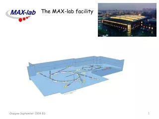
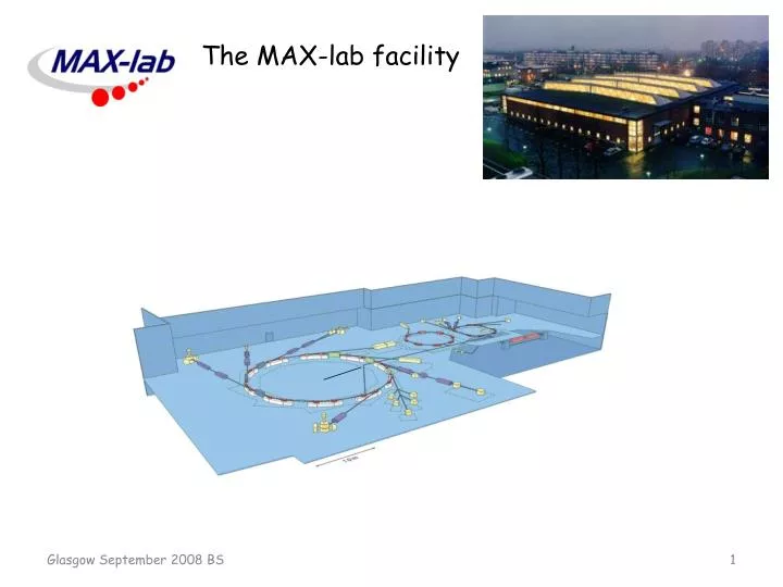
The MAX-lab facility. The MAX-lab facility. MAX I storage ring (550 MeV)/stretcher 1986 MAX II storage ring (1.5 GeV) 1995 MAX III storage ring (.7 GeV) 2007 FEL (test facility) 2007 MAX IV proposal 2007 ( VR governement). MAX I. MAX III. MAX II. Injector. FEL. Nuclear Physics area.

E N D
The MAX-lab facility MAX I storage ring (550 MeV)/stretcher 1986 MAX II storage ring (1.5 GeV) 1995 MAX III storage ring (.7 GeV) 2007 FEL (test facility) 2007 MAX IV proposal 2007 (VR governement) MAX I MAX III MAX II Injector FEL Nuclear Physics area 40 weeks per year SR at MAX II, MAX III 22 weeks per year SR at MAX I 18 weeks per year nuclear physics at MAX I (4 x 4 weeks + 1 x 2 weeks)
MAX-lab Staff: 80 PhD students located at MAX-lab: 13 MAX-lab is a national facility funded by the Swedish Research Council (VR 50 MSEK) and Lund University (20 MSEK). Two Divisions belonging to the Natural Science Faculty: Accelerator Physics and Instrumentation for Synchrotron Radiation Research, are placed at MAX-lab. MAX-lab is foremost a synchrotron radiation facility.
Injector overview To MAX I 500 MeV 250 MeV linac gun linac gun chicane Two linacs with a recirculator for injection into MAX II and MAX III. Nominal: 125 MeV per linac Actual: 100 MeV per linac Space limitations prevent recirculation for injection into MAX I recirculator
For nuclear physics, the linacs operate at 10 Hz giving an electron pulse some 100-200 ns wide. The electron beam is injected into the stretcher ring MAX I. The electron beam is extracted slowly during the 100 ms interval between pulses from the injector. The stored electrons are ”shaked” and move towards the thin extraction septum. The average beam current in the ring is about 20 mA, resulting in an extracted current of 20 nA (106 ). Cavity to compensate synchrotron light losses in the dipole magnets Lars-Johan Lindgren
The synchrotron light from a bending magnet observed with a CCD camera. The division is 20 ms. The electrons in the ring are almost entirely extracted between injections. The extracted beam seen by a nuclear detector in the experimental area. Shown is a TDC spectrum started by the linac trigger and stopped by an event in the detector (in this case a NaI(Tl)). The spectrum was obtained during a tagging efficiency measurement with the NaI detector as trigger. Part of the events are accidentals from cosmic radiation.
Experimental area Shielding indicated by DIANA BUNI CATS
SAL tagging spectrometers 50o magnet 30o dipole Beam dump FC Ee Focal plane hodoscope E’ radiator Dump magnet ET radiator Photon beam Eg = Ee – E’ MT Scale: 6 m between pillars MT: Main tagger ET: EndPoint tagger FC: Faraday cup Eg
Main Tagger The MT settings are determined by the magnetic field in the tagging magnet Setting 340 MT Setting 460 setting 340 setting 460 ET
SAL focal plane hodoscope DEg= (95-31)/62≈ 1 MeV MT setting 340 31 MeV 95 MeV Ee = 188,5 (MeV) The focal plane hodoscope consists of 63 scintillators with 50 % overlap resulting in 62 channels.
The collimator arrangement for the November - December 2006 deuterium run. distance to ET radiator: 3 585,3 mm distance to MT radiator: 1 689,5 mm cell center 144 3299,5 400 Lead brick 2485 MT vacuum Collimator assembly Target 125 45 The collimator assembly consists of a heavymet main collimator, 108.5 mm long, with an entrance opening of 12 mm and an exit opening of 13 mm. The outer diameter of the main collimator is 80 mm. With the collimator inset used, the opening angle is 3,3 mr. The beam spot size at the target position is then expected to have a diameter of 37 mm. This agrees well with photos taken during the deuterium run. Glasgow September 2008 BS
Coherent bremsstrahlung The location of the focal plane for three different positions of the radiator at the MT. Old target 6.55 cm refers to the SAL radiator wheel in the normal position slightly inside the magnetic field. Old target -18.55 cm refers to the SAL radiator wheel in a position outside teh magnetic field after a 180o rotation of the wheel. Crystal -26.5 cm refers to the position of the center of the goniometer. Dmytro Pugachov Glasgow September 2008 BS
New radiator chamber The electron beam Goniometer The goniometer may be removed and replaced by the SAL radiator wheel within a few hours. Glasgow September 2008 BS
Two 2 week periods have been used for commissioning of the coherent beam with the participation of the Kharkov group and Ken Livingstone from Glasgow. Vladimir Ganenko will report on these tests. The project was supported by the I3HP JRA3 EuroTag funding a postdoc, Dmytro Pugachov, for two years. The equipment was funded by the Swedish Research Council and the Royal Physiographic Society in Lund. The goniometer at MAX-lab Glasgow September 2008 BS
Magnus Lundin, Thesis; http://www.maxlab.lu.se/kfoto/Publications/Thesis/lundin.pdf
TOF spectrum from Carbon with an energy cut selecting elastically scattered photons. The structure separated by 305 ns is caused by the shaker (3.3 MHz). The structure separated by 108 ns is caused by uneven filling of the ring (circumference 32 m).
Tagging efficiency Luke Myers
Proposed experiments in December 2004 Proposal No. 1 Photodisintegration of Li-isotopes Proposal No. 2 the total photoabsorption cross section of 6,7Li below p-threshold Proposal No. 3 Compton scattering from 4He and 12C Proposal No. 4 PARTIAL REACTIONS OF PION PHOTOPRODUCTION AT LIGHT NUCLEI Proposal No. 5 Measurement of Photoreactions on Helium Isotopes using Gas-Scintillator Active Targets Proposal No. 6 Elastic Compton Scattering from Deuterium at 40-110 MeV Proposal No. 7 Threshold Neutral Pion Photoproduction in Hydrogen and Deuterium Proposal No. 8 Photofission of Heavy Actinide Nuclei at MAX-Lab Proposal No. 9 Low-pressure MWPC Technique in Nuclear Experiments with Electron and Photon Probe Proposal No. 10 INITIAL COMMISSIONING OF THE Ge6 ARRAY AT MAXLAB Proposal No. 11 Study of the Halo Nucleus 6He using the 6Li(g,p+)6He Reaction Proposal No. 12 Deeply Bound Pionic Atoms from the (g,p) Reaction Proposal No. 13 High-resolution Measurement of the 4He(g,pn) Reaction Proposal No. 14 Charged Pion Photoproduction from Threshold up to the First-Resonance Region + a few more in 2006.
Run Reports Runperiod 1 2005.05.09 - 2005.06.06 Runperiod 2 2005.09.19 - 2005.10.03 Runperiod 3 2005.10.17 - 2005.10.31 Runperiod 4 2005.12.05 - 2005.12.19 Runperiod 5 2006.02.13 - 2006.03.13 Runperiod 6 2006.04.24 - 2006.05.22 Runperiod 7 2006.10.16 - 2006.11.06 Runperiod 8 2006.11.27 - 2006.12.18 Runperiod 9 2007.02.12 - 2007.03.12 Runperiod 10 2007.04.16 - 2007.04.30 Runperiod 11 2007.05.28 - 2007.06.25 Runperiod 12 2007.09.10 - 2007.10.08 Runperiod 13 2007.11.05 - 2007.12.03 Runperiod 14 2008.02.18 - 2008.03.17 Editor: Kevin Fisum
New focal plane hodoscope An application to the Knut and Alice Wallenberg Foundation was submitted in December 2007 and funded in June 2008. The design is very similar to the Glasgow design for the tagger in Mainz. We will use the same electronic boards designed by John Annand and the same Hamamatsu 10 mm diameter PM tubes. The application also covers new data aquisition equipment. The length of the focal plane for the MT is 1240 mm, and for the ET 1330 mm. We will build a 1200 mm long hodoscope with 160 scintillators, each 3 x 10,5 x 60 mm. Glasgow September 2008 BS
MT ET 15 mm diameter Glasgow September 2008 BS
The Lund design (the cards are not shown) limited by the requirement that the scintillator array must be rotated. Mainz Glasgow September 2008 BS
Overview of the Lund focal plane hodoscope with the actual dimensions of the electronic cards seen in the photo. Glasgow September 2008 BS
Design goals: electron energy 100 – 250 MeV intensity 40 nA Ng~ 1 MHz/MeV 75 % duty cycle Today: electron energy 144 – 200 MeV intensity 30 nA Ng ~ 0.5 MHz/MeV 75 % duty cycle Remaining issues: maximum electron energy time structure in the beam
The local nuclear physics group (Jason Brudvik, Kevin Fisum, Kurt Hansen, Lennart Isaksson, Magnus Lundin and BS) acknowledge the support by the European Community - Research Infrastructure Action under the FP6 "Structuring the European Research Area" Programme (through the Integrated Infrastructure Initiative "HadronPhysics"), and furthermore the support by the Swedish Research Council, the Craaford Foundation, the Wennergren Foundation, the Royal Physiographic Society in Lund and the Knut and Alice Wallenberg Foundation.
Beam monitors In-beam monitor, John Annand PILATUS, Roger Rassool, Vivien Lee, Roger Peake CCD camera, Kurt Hansen, Jenny Ber, Claire Van Ngoc Ty
This in-beam monitor is used for experiments upstream of the target. The ratio between the count rate of the in-beam monitor and the count rate in the focal plane is proportional to the tagging efficiency and may be used to monitor this quantity during a run. John Annand
The pixel apparatus for the SLS is a novel type of X-ray detector developed at the Swiss Light Source. It is a two-dimensional hybrid pixel array detector operating in a single-photon counting mode. The module used at MAX-lab is composed of approximately 100 000 172 mm square pixels arranged in a matrix 487 x 192. It comprises a preamplifier, a comparator and a counter. The readout time is 5 ms. The count rate may be as high as 1,5 MHz/s/pixel. The detector is mainly sensitive to X-rays with energies below 20-50 keV.
The socalled time in pulse spectrum. A TDC is started by the machine trigger and stopped by a recoil electron in the focal plane hodoscope.
Poor (wo)man’s version of PILATUS ASTOVID StellaCam IITM CURIX ORTHO FINE Gadolinium A Win TV Express from Hauppauge produces 25 frames per second at a resolution 384 x 288 pixels on the computer screen. Frames may be grapped and saved as a jpeg file. The TV card is controlled with a C/C++ program using root for the processing and for the graphics. http://www.maxlab.lu.se/kfoto/Publications/Master/berg.pdf
Threshold set at 100 Threshold set at 0
Threshold set at 90 The beam is moved in the vertical direction