Download
1 / 20
200 likes | 403 Views
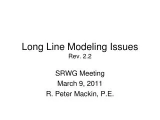
Long Line Modeling Issues Rev. 2.2. SRWG Meeting March 9, 2011 R. Peter Mackin, P.E. Background. Basic Transmission Line Models (from Stevenson, Elements of Power System Analysis, 4 th Edition) Short Transmission Line: Up to 50 miles. Z = R + jX. Background.

E N D
Long Line Modeling IssuesRev. 2.2 SRWG Meeting March 9, 2011 R. Peter Mackin, P.E.
Background • Basic Transmission Line Models • (from Stevenson, Elements of Power System Analysis, 4th Edition) • Short Transmission Line: • Up to 50 miles Z = R + jX
Background • Medium-length Transmission Line: • 50 miles to 150 miles Z = R + jX Y 2 Y 2
Background • Long Transmission Line: • Greater than 150 miles • Lumped parameters cannot be used accurately to represent these lines • Accurate representation requires the use of hyperbolic functions sinh(γl) γl Z’ = Z Y’ 2 Ytanh(γl/2) 2 γl/2 Y’ 2 =
The Issue • For long transmission lines (greater than say 150 miles), using the per mile impedance times the line length in miles can result in an inaccurate representation of the transmission line. • For these long lines, it is better to use the “long line” equations that involve hyperbolic functions to calculate the line impedance. • A couple of examples that illustrate the problem are given below.
Example #1 • Assume a new 500 kV line with the following parameters • 200 miles long • Horizontal conductor configuration • 32’ phase spacing, 35’ minimum clearance to ground • 3 – 1780 ACSR 84/19 “Chukar” conductors per phase • 18” triangular bundle
Example #1 • The table below shows the impedances for this line calculated using either the PowerWorld Transmission Line Parameter Calculator (TLPC) ver. 1.0 or Aspen Line Constants. • The PowerWorld TLPC uses “Long Line” equations to calculate more accurate values of impedance and admittance for longer lines. • Aspen Line Constants calculates a “per mile” impedance and then multiplies this value by the line length in miles to determine the line impedance and admittance.
Example #1 • The example below shows the effects of the different impedance assumptions on the flow on this hypothetical line. • The first power flow plot shows the flows on the line when using the “long line” impedance and admittance. • The second power flow plot shows the flows on the line in the first plot when a new bus is added 60% of the total line distance from TESTBUS1. • The third power flow plot shows the flows on the line when using inaccurate “per mile” impedance and admittance method used by Aspen Line Constants. • The fourth power flow plot shows the flows on the line in the third plot when a new bus is added 60% of the total line distance from TESTBUS1.
Example #1 • This power flow plot shows the flows on the line when using the “long line” impedance and admittance. Parallel Paths Long Line Parameters
Example #1 • This power flow plot shows the flows on the line in the first plot when a new bus is added 60% of the total line distance from TESTBUS1. Parallel Paths Long Line Parameters
Example #1 • This power flow plot shows the flows on the line when using inaccurate “per mile” impedance and admittance method used by Aspen Line Constants. Parallel Paths Per Mile Line Parameters
Example #1 • This power flow plot shows the flows on the line in the third plot when a new bus is added 60% of the total line distance from TESTBUS1. Parallel Paths Per Mile Line Parameters
Example #1 Conclusions • As shown, “long line” impedance and admittance values provide the most accurate results for long lines. This conclusion can be observed by noting that the line flows before and after adding an intermediate bus to a line are almost exactly the same. • Using “per mile” impedance and admittance values are not as accurate. This fact is demonstrated by the addition of an intermediate bus to the line using these parameters. As shown in the third and fourth power flow plots, the flow on the line is not the same in both cases (even though it should be).
Example #2 • The first power flow plot shows the line flows on a 200 mile long 500 kV line that is modeled as 5 series pi sections of 40 miles each. • The second power flow plot shows the line flows on a 200 mile long 500 kV line that is correctly modeled as 1 long line compensated segment (i.e., using PowerWorld Transcalc). • The third power flow plot shows the line flows on a 200 mile long 500 kV line modeled as 1 Pi segment (incorrectly modeled using per mile impedances times line length in miles). • The fourth power flow plot shows the line flows on a 200 mile long 500 kV line that was originally modeled using long line compensated impedances (Example #2, Plot #2), but is now split into two equal segments without recalculating the segment impedances. (This example is different than Example #1 in that the long line compensated impedances were simply divided in half. In example #1 the long line impedances were recalculated when adding the intermediate bus.)
200 Miles of 500 kV line modeled as 5 series Pi sections of 40 Miles each Parallel Paths The first power flow plot shows the line flows on a 200 mile long 500 kV line that is modeled as 5 series pi sections of 40 miles each.
200 Miles of 500 kV line modeled as 1 long-line compensated segment Parallel Paths The second power flow plot shows the line flows on a 200 mile long 500 kV line that is correctly modeled as 1 long line compensated segment (i.e., using PowerWorld Transcalc).
200 Miles of 500 kV line modeled as 1 Pi segment (Incorrectly Modeled) Parallel Paths The third power flow plot shows the line flows on a 200 mile long 500 kV line modeled as 1 Pi segment (incorrectly modeled using per mile impedances times line length in miles).
200 Miles of 500 kV line split into two segments without recalculating the long line impedances Parallel Paths The fourth power flow plot shows the line flows on a 200 mile long 500 kV line that was originally modeled using long line compensated impedances (Example #2, Plot #2), but is now split into two equal segments without recalculating the segment impedances. (This example is different than Example #1 in that the long line compensated impedances were simply divided in half. In example #1 the long line impedances were recalculated when adding the intermediate bus.)
Example #2 Conclusions • GE PSLF properly corrects impedances for long lines if the line is split into multiple short segments (compare Plots #1 and #2). • Incorrectly modeling a long line using per mile impedances times line length in miles results in slightly different (and incorrect) flows on the modeled line. • If you add an intermediate bus to a long line, you must recalculate the new line impedances. You cannot just multiply the impedances by the ratio of the distance to the next bus divided by the total line length. This conclusion applies whether the original impedance was calculated using long line compensated impedances or “per mile” impedances.