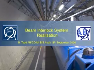
Realising the SMP
420 likes | 610 Views
Realising the SMP. 1. Safe Machine Parameters Overview Basics Piggy-Back on GMT. 2. Evolution to the Proposal Basic Architecture Enhanced Architecture. 3. Electrical Realisation CISP Back Panel CISX Base Board. 4. Partition of workload January 2008. Realising the SMP.

Realising the SMP
E N D
Presentation Transcript
Realising the SMP 1. Safe Machine Parameters Overview • Basics • Piggy-Back on GMT 2. Evolution to the Proposal • Basic Architecture • Enhanced Architecture 3. Electrical Realisation • CISP Back Panel • CISX Base Board 4. Partition of workload • January 2008 Safe Machine Parameters System
Realising the SMP 1. Safe Machine Parameters Overview • Basics • Piggy-Back on GMT 2. Evolution to the Proposal • Basic Architecture • Enhanced Architecture 3. Electrical Realisation • CISP Back Panel • CISX Base Board 4. Partition of workload • January 2008 Safe Machine Parameters System
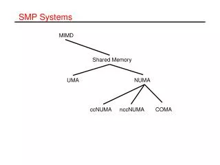
Safe Machine Parameters Several Safety Critical flags and values are needed around the LHC (see Bruno) -Initially a dedicated high-dependability communications system was proposed -it became clear that this would be a huge system having lots of infrastructure to maintain -finally it was decided to send these signals through the CERN General Machine Timing (GMT) The signals are generated externally and pushed into the GMT generator (CTG) … They are queued… They are sent… They are received all around the machine… (in a CTRV or CTRP) Safe Machine Parameters System
Good motivation for GMT Comms Errors Data given to GMT could be wrong GMT could corrupt data Front-End could corrupt data Safe Machine Parameters System
Good motivation for GMT Comms Errors Data given to GMT could be wrong Make a dependable source Bit Error Rate of GMT can be calculated Mean Time to Fail estimated Failure Mode estimated GMT could corrupt data Front-End could corrupt data Read-back and compare to source Safe Machine Parameters System
Realising the SMP 1. Safe Machine Parameters Overview • Basics • Piggy-Back on GMT 2. Evolution to the Proposal • Basic Architecture • Enhanced Architecture 3. Electrical Realisation • CISP Back Panel • CISX Base Board 4. Partition of workload • January 2008 Safe Machine Parameters System
The basic function of the SMP… Safe Machine Parameters System
The first step is to accommodate multiple data sources to increase dependability… Safe Machine Parameters System
Then duplicate the critical processes Safe Machine Parameters System
The transmitter must then arbitrate the data from the two sources Safe Machine Parameters System
Finally the output GMT must be cross-checked with the original data Safe Machine Parameters System
Finally the output GMT must be cross-checked with the original data Safe Machine Parameters System
Realising the SMP 1. Safe Machine Parameters Overview • Basics • Piggy-Back on GMT 2. Evolution to the Proposal • Basic Architecture • Enhanced Architecture 3. Electrical Realisation • CISP Back Panel • CISX Base Board 4. Partition of workload • January 2008 Safe Machine Parameters System
Flag Generator – CISG Frame Receiver – CISR Generator Arbiter – CISA Flag Generation Safe Machine Parameters System
SMP Transmission Cross-Checker – CISC Timing Receiver - CTRV Flag Cross-Checking Safe Machine Parameters System
A Standard VME Chassis Has 21 Slots! A summary of those devices shown on the previous slides Frame Receiver – CISR Flag Generator – CISG Generator Arbiter – CISA Generator Arbiter B - CISB SMP Transmission Cross-Checker – CISC Chassis Debugger – CISD Timing Receiver - CTRV Safe Machine Parameters System
A Standard VME Chassis Has 21 Slots! A summary of those devices shown on the previous slides Frame Receiver – CISR Flag Generator – CISG Generator Arbiter – CISA Generator Arbiter B - CISB SMP Transmission Cross-Checker – CISC Chassis Debugger – CISD Timing Receiver - CTRV SMP Phase IV Generator Arbiter B – CISB Can link SPS SMP System to the LHC GMT Can link the LHC SMP System to the SPS GMT Safe Machine Parameters System
A Standard VME Chassis Has 21 Slots! Frame Receiver – CISR Flag Generator – CISG Generator Arbiter – CISA Generator Arbiter B - CISB SMP Transmission Cross-Checker – CISC Chassis Debugger – CISD Timing Receiver - CTRV X4 (side by side) X2 (after CISR) X1 (after CISG) X1 (after CISG) X1 (after CTRV) X2 (gen and check) X3 14 slots used Safe Machine Parameters System
The rules of engagement • Several PCBs will be needed • rely on existing technology and ideas. Don’t reinvent the wheel! • See 1. • Diagnosis and Monitoring needed • Test modes needed • System will be in one location, no need for remote update • System will be built twice (plus spares) manufacturability NOT hugely critical • CPLD / FPGA technology = good • VHDL/Schematic Entry = good • Displays / debuggingaccess = good • Elegant design, robust and ergonomic = good • PCAD = good • Design office = not so good 12b. Documentation is very very good. Safe Machine Parameters System
CISP - Backplane • Everything fits into a single VME Chassis • Is the P2 backplane idea a necessity? • Is it possible to reduce the complexity of the system by integration? • Is it possible to use a single board for the base of the system? YES! YES! YES! Safe Machine Parameters System
CISP Front View Safe Machine Parameters System
CISP – P2 Connectors Safe Machine Parameters System
CISP – Burndy Connectors Safe Machine Parameters System
CISP – Burndy Connectors Local Flags (for connections to the Beam Interlock System) 8 flags from the Generators Internal Flags for Failure Safe Machine Parameters System
P2 to CISP with CIBEA CIBEA is the basis for the design! 3x32 (Panel) 5x32 (VME P2) 92 signals = 46 differentials Safe Machine Parameters System
CISX – A Standard PCB The requirements can be accommodated on a single PCB… • We must determine the topology of the Programming Chain • We must determine the use of PROM/FLASH/CPLD for Thresholds • -How is it accessed • -How is it checked • -How is it updated in the field • -How do we guard against Single Event Upsets • (Grey Counters or Hardware etc) • 3. Non-Volatile storage of History Buffer done at the same time • 4. Nice display option for EVERY card. • Good for debug Safe Machine Parameters System
CISX Standard 160, 6U board Safe Machine Parameters System
CISX VME Electrical Interface & Power Supply Safe Machine Parameters System
CISX FPGA and PROM, JTAG and Display Safe Machine Parameters System
CISX RS422 / Clocks/ Remote Update Safe Machine Parameters System
CISX Current Loops and terminations Safe Machine Parameters System
CISX FLASH Safe Machine Parameters System
CISX Display Safe Machine Parameters System
CISX 50-Ohm Inputs Safe Machine Parameters System
CISX CIBO Safe Machine Parameters System
CISX – A Standard PCB Three Different Assemblies Safe Machine Parameters System
Time-Scale Phase I – Deadline October / November 2007 Specify I/O of Chassis Specify Internal Layout of Chassis Specify Electrical Level Architecture for Whole Chassis Build simple Prototype based in the LAB Phase II – Deadline February / March 2008 Expand Prototype to include redundancy Develop Fail-safe, Monitoring and Test Mode in the LAB and SPS Phase III – Deadline Summer 2008 Include all Safety Aspects Include all FESA type Monitoring In the LAB, SPS and when completed roll out to LHC Phase IV – Deadline Summer 2009 Include revisions for operations. Already know we have to connect SPS -> LHC and vice-versa SMP 1v0 SMP 2v0 SMP 3v0 Safe Machine Parameters System
Time-Scale Phase I – Deadline October / November 2007 Specify I/O of Chassis Specify Internal Layout of Chassis Specify Electrical Level Architecture for Whole Chassis Build simple Prototype based in the LAB Phase II – Deadline February / March 2008 Expand Prototype to include redundancy Develop Fail-safe, Monitoring and Test Mode in the LAB and SPS Phase III – Deadline Summer 2008 Include all Safety Aspects Include all FESA type Monitoring In the LAB, SPS and when completed roll out to LHC Phase IV – Deadline Summer 2009 Include revisions for operations. Already know we have to connect SPS -> LHC and vice-versa SMP 1v0 SMP 2v0 SMP 3v0 Safe Machine Parameters System
Realising the SMP 1. Safe Machine Parameters Overview • Basics • Piggy-Back on GMT 2. Evolution to the Proposal • Basic Architecture • Enhanced Architecture 3. Electrical Realisation • CISP Back Panel • CISX Base Board 4. Partition of workload • January 2008 Safe Machine Parameters System
Who is doing what? Frame Receiver – CISR - Alex Flag Generator – CISG - Ben Generator Thresholds Board - Ivan Generator Arbiter – CISA - Alex Generator Arbiter B - CISB SMP Transmission Cross-Checker – CISC Chassis Debugger – CISD - Bertrand We are on track… SMP 1v0 was done (electrically sound). SMP 2v0 is in the pipeline (4 CISX & 2 Chassis here next week) Safe Machine Parameters System
FIN Safe Machine Parameters System