Download
1 / 23
240 likes | 462 Views
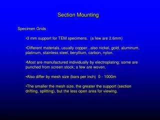
Section Mounting. Specimen Grids 3 mm support for TEM specimens. (a few are 2.6mm) Different materials..usually copper...also nickel, gold, aluminum, platinum, stainless steel, beryllium, carbon, nylon.

E N D
Section Mounting • Specimen Grids • 3 mm support for TEM specimens. (a few are 2.6mm) • Different materials..usually copper...also nickel, gold, aluminum, platinum, stainless steel, beryllium, carbon, nylon. • Most are manufactured individually by electroplating; some are punched from screen stock; a few are woven. • Also differ by mesh size (bars per inch) 0 - 1000m • The smaller the mesh size, the greater the support (section drifting, splitting), but the less open area for viewing.
Section Mounting • A 200m grid has 60% open area; a 400m grid only 40% • Thin-bar grids...more fragile, more expensive. • Ultrathin sections can be supported on a bare grid of no greater than 200m. • Commonly used TEM grid types:
Picking up sections Slot grids Mesh grids Slot grids: typically come up from bottom. Mesh grids: either from under or top (naked). If coated, from under.
Collecting on slot grids Dried on bridge, then punched out for viewing Sections floating on water
SectionMounting An ultrathin section on a 50m support filmed grid at 200X mag.
Support Films Formvar, Carbon, Collodion -Used when sections or samples are smaller than support of grid. -100 mesh or less, slot grids -Fragile or very thin sections Avoid when possible because: Usually has holes or uneven thickness Added thickness affects clarity and contrast
Formvar coated grids Holey formvar Formvar and carbon
Contrast • Light Microscopy • Contrast achieved by: • Use of special optics and filters which impart selective colors or brightness to areas differing in thickness or composition. E.g. - phase contrast, D.I.C. optics. Phase contrast
Contrast achieved by: • Selective staining • Chromatic stains selectively bind to specific components in the specimen. E.g. - Hematoxylin/Eosin
Contrast • Transmission Electron Microscopy: • Contrast is produced by the adsorption of heavy metals to specimen macromolecules. • The ability of an atom to absorb electrons is directly related to its mass. • Since biological specimens are composed mostly of low atomic # elements (C,O,H,N), they lack endogenous contrast....thus contrast is induced by "staining" with heavy metals. • Microscopists refer to the measure of a specimen's ability to absorb electrons as its electron density (vs electron “transparency”).
Contrast • Transmission Electron Microscopy: • Heavy metals commonly used for contrasting in TEM: uranium, lead, osmium, ruthenium, molybdenum, gold, silver. • It is the differential adsorption of various heavy metals to tissue components that produces the electron image of biological thin-sectioned materials. • The image may be composed of areas ranging from completely black to completely white with all ranges of grey in between. • Images with mostly pure blacks and whites are "contrasty" images, while those containing mainly greys are "flat” images.
Post-Staining • Typically always used, even if enbloc staining (ie uranyl acetate) has been done. • Uranyl acetate - 0.5 - 2% aqueous. Also can use saturated ethanolic or methanolic UA • Lead citrate - several formulations (Venable and Coggeshell or Reynolds). Common is using lead nitrate chelated with sodium citrate. • Adequate rinsing between and after staining is essential to prevent post-stain contamination. Particular care must be used to exclude CO2 to inhibit lead carbonate formation - black cannonballs.
Staining with UA Lead staining • Typical protocol: • - 30 minutes UA • - Wash with water • - 5 minutes lead citrate • - Wash once in 0.02M NaOH • Wash well with water. • Dry by wicking with filter paper
Negative Staining Positive staining - forms a complex with specimen Negative - stain and specimen do not interact and specimen remains electron transparent Advantages: 1) Improved resolution 2) Speed 3) Unique information 4) Simplicity
Disadvantages: 1) Repeatability 2) Limited surface topography 3) Toxicity
Choice of stain: 1) High density to provide high contrast 2) High solubility and minimal reaction to sample 3) High melting and boiling point (beam stable) 4) Precipitant formed is extremely fined grained Stains commonly used: Phosphotungstate, sodium tungstate, uranyl acetate and uranyl nitrate
Brief procedure: Small grid and support film (formvar, paraloidin. Sometimes carbon added. Thin suspension of sample and excess removed. Dry then add negative stain and remove Factors affecting staining: concentration of stain pH of stain time - Dry and view.
Negative stain of purified RhMV virus labelled with anti-RhMV and detected with anti- rabbit conjugated to 10 nm gold. Bar = 100 nm. Photograph provided by Fred Gildow Lab, Department of Plant Pathology, Penn State.