Automated ADM with micrometer accuracy using the Michelson interferometer
300 likes | 721 Views
Automated ADM with micrometer accuracy using the Michelson interferometer. Coherent and Electro-Optics Research Group (CEORG) K Alzahrani, D Burton, M Lalor , F Lilley, F Bezombes , and M Gdeisat. Outlines. Introduction Project objective Basic principles Michelson interferometer

Automated ADM with micrometer accuracy using the Michelson interferometer
E N D
Presentation Transcript
Automated ADM with micrometer accuracyusing the Michelson interferometer Coherent and Electro-Optics Research Group (CEORG) K Alzahrani, D Burton, M Lalor, F Lilley, F Bezombes, and M Gdeisat
Outlines • Introduction • Project objective • Basic principles • Michelson interferometer • ADM using the Michelson interferometer • Challenges • Future work • Conclusion
Introduction • Conventional interferometry can only determine relative distance measurements – i.e. it can only determine how much further away one point is compared to another point, provided that both points are linked by a continuous path. • Absolute distance interferometry (ADI)can measure the distance between any two arbitrary points.
Project objective Building a fully automated ADM system, with micrometer or better measurement accuracy, over comparatively large distances of up to 40 meters.
Basic principles • Interference • Coherence length • Synthetic wavelength
Interference • Light consists of burst of sine waves. • Two light waves derived from the same source and projected onto a point may interfere if interference conditions have been met. • The interference could be constructive or destructive.
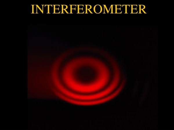
Interference • Similarly two light waves derived from the same source and projected onto a surface may also interfere to produce fringes if interference conditions have been met. As in Young’s double-slit experiment.
Coherence length • Light source emits light as finite length trains. • The phase of the sine wave changes randomly. • The distance between two consecutive trains is called the coherence length. • The longer the trains the more coherent the light source.40 m for the used laser.
Synthetic wave • Two light waves with different wavelengths, start with the same phase will become out of phase and then in phase regularly. We refer to the length over which this happens as synthetic wavelength s . s = (21/2-1 )
Synthetic wave formation 1 = 100nm, 2 =120nm s =600nm
Michelson interferometerconstruction • The Michelson interferometer produces interference fringes by splitting a beam of monochromatic light so that one beam strikes a fixed mirror and the other strikes a movable mirror.
Michelson interferometerDisplacement measurement • In a conventional displacement measurement, laser wavelength is held fixed and the interferometer system counts fringes as a reflector is displaced.
Michelson interferometerscenario.1 • Laser operates at a fixed wavelength . • Let l1=l2, grab 1st image • move the adjustable mirror to make l1≠l2,grab 2nd image • There is a phase difference between both patterns . • l =l1-l2 • l =0 then =0 • l = /4then = π • l = /2then =2π
Michelson interferometer scenario.2.a • The arms of the interferometer is held fixed while the light wavelength is changed. • Let l1=l2 , two fringe patterns are produces at 1 and 2. • =0
Michelson interferometer scenario.2.b • Let l1 ≠ l2, laser operates at 1 and 2 • Two fringe patterns are produced at 1 and 2. • There is a phase shift between both fringe patterns.
The algorithm • Suppose that we estimate lr and lmand we know l with precision of . • Laser operates at 1,grab 1st image • Laser operates at 2,grab 2snd image • we can determine l with accuracy of . Using the following equation l= Ns + f s where f= /2π • Repeating this routine several times with reduced we will determine l with increasing accuracy.
Example • l ≃100mm,with =0.5mm. 1 =685nm grab the 1st image. • 2 must satisfy the condition s = 2 • s = 1mm,δ =(1)/(s-1 )=0.47nm,2= 685.47nm grab 2nd image • measure =1.9 rads (0.3 s ) • ΔL must lie between 99.5mm and 100.5mm
N1=|l - /s| and N2=|l + /s| then N1=99 & N2=100. Combining these to and s, l 1=99.3mm,l 2 =100.3mm. l 1 lies out of the tolerance range , therefore l =100.3mm 2nd iteration /2=0.25mm,l lies between two values with 0.5mm difference. And according to N1 and N2 we choose one value that falls in the tolerance range and so on. Several iterations l can be determined with increasing accuracy.
System components • A tunable laser with a tuning range of 680.4 nm to 691 nm. • The wavelength can be changed with an accuracy of 0.1 nm. • A wavelength meter with an accuracy of 0.0001 nm. • A monochrome camera with a resolution of 1024X1360 pixels. • Michelson interferometer.
The absolute length measurement system The system is completely controllable from the computer. Using IDL software, we can set the tunable laser, read the wavelength and grab fringe patterns in less than one second. The tunable laser requires five seconds approximately to settle down.
Achievements • A significant amount of work has been put into building the system and calibrating it. • An initial attempt was made to control the system using a semi-automated approach and it was partially successful. • With the semi-automated system, setting the laser, reading the wavelength and grabbing an image takes at least 10 minutes for each iteration. • The full iterative measurement process takes around two hours.
Achievements • Very recently, we managed to control the system completely from the IDL software. • The system is now ready to use. • With the IDL system, setting the laser, reading the wavelength and grabbing an image takes less than one second. • The tunable laser requires five seconds approximately to settle down. • The full iterative measurement process requires less than 30 seconds.
Future work • The use of multi-wavelengths instead of two wavelengths will be investigated. • At the moment, we are able to measure the absolute distance for one point with m accuracy. This capability will be extended to measure the absolute distance for a surface.
Conclusion • A new absolute length measurement system is proposed and a patent application is underway for this system. • The hardware of the system has been built completely in GERI labs from scratch and is completely automated using IDL software. • The operation principle has been verified mathematically and experimentally. • The system offers 4 micrometers or better measurement accuracy over distances up to 40 meters. • Future work will be carried out to improve the performance of this system and extend its capabilities.