Download
1 / 30
300 likes | 461 Views
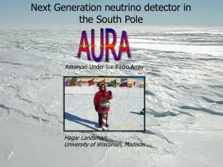
AURA. Askaryan Under-Ice Radio Array. Next Generation neutrino detector in the South Pole. Hagar Landsman, University of Wisconsin, Madison. Outline . A skaryan. Askaryan Effect and neutrino detection. U nder ice. Why Ice? Why Radio?. R adio. Radio detection. A rray.

E N D
AURA Askaryan Under-Ice Radio Array Next Generation neutrino detector in the South Pole Hagar Landsman, University of Wisconsin, Madison
Outline Askaryan Askaryan Effect and neutrino detection Underice Why Ice? Why Radio? Radio Radio detection Array Experiment Design and prospective
Tribute to ATLAS@LHC.CERN The Future: Hybrid Detector ~10 km Ice Cube ~ 1km 25 m 45 m
Quest for UHE neutrinos • GZK Cut-off p+gCMB • No cosmic rays from proton above 1020 eV • As a by-product – neutrino flux • A non detection will be even more exciting • Point Sources of neutrinos • Dark matter
Why so big? • To detect 10 GZK events/year, a detection volume of 100 km3 ice is needed. • A larger detector requires a more efficient and less costly technology. • Alternative options include radio and acoustic detection.
Askaryan effect Hadronic (initiated by all n flavors) EM (initiated by an electron, from ne) Neutrino interact in ice showers Many e-,e+, g Vast majority of shower particles are in the low E regime dominates by EM interaction with matter Interact with matter Excess of electrons Cherenkov radiation Less Positrons: Positron in shower annihilate with electrons in matter e+ +e- gg Positron in shower Bhabha scattered on electrons in matter e+e- e+e- More electrons: Gammas in shower Compton scattered on electron in matter e- + g e- +g Coherent for wavelength larger than shower dimensions Moliere Radius in Ice ~ 10 cm: This is a characteristic transverse dimension of EM showers. <<RMoliere (optical), random phases P N >>RMoliere (RF), coherent P N2 Charge asymmetry: 20%-30% more electrons than positrons.
LPM effect Landau-Pomeranchuk-Migdal As the energy increases, the multiplicity of the shower increases and the charge asymmetry increases. As the energy increases, mean free path of electrons is larger then atomic spacing (~1 PeV) (LPM effect). Cross section for pair production and bremsstrahlung decreases longer, lower multiplicity showers • The Neutrino Energy threshold for LPM is different for Hadronic and for EM showers • Large multiplicity of hadronic showers. Showers from EeV hadrons have high multiplicity ~50-100 particles. • Photons from short lived hadrons • Very few E>100 EeV neutrinos that initiate Hadronic showers will have LPM • In high energy, Hadronic showers dominate • Some flavor identification ability
Salt Ice Typical pulse profile Strong <1ns pulse 200 V/m Simulated curve normalized to experimental results Measurements of the Askaryan effect • Were preformed at SLAC (Saltzberg, Gorham et al. 2000-2006) on variety of mediums (sand, salt, ice) • 3 Gev photons are dumped into target and produce EM showers. • Array of antennas surrounding the target Measures the RF output • Results: • RF pulses were correlated with presence of shower • Expected shower profiled verified D.Salzberg, P. Gorham et al. • Expected polarization verified (100% linear) • Coherence verified. • New Results, for ANITA calibration – in Ice
Radio Ice, no bubbles (1.5-2.5 km) optical Effective Volume per Module (Km3) Astro-ph/9510119 P.B.Price 1995 Water (Baikal 1km) Acoustic Ice, bubbles (0.9 km) 1015 1016 1014 1013 1012 Energy (eV) Why Ice? Why Radio? • Long attenuation - Radio ~1km • Optical attenuation in ice 100m • No scattering for Radio In ice. • A lot of it. • Free to use. • South pole is isolated. RF quiet. • Antennas are cheaper and more robust than PMTs. • No need to drill wide holes lower drilling cost of deployment w.r.t optical detectors 1016 - ~1023 eV 1017 Effective volume per detector element for ne induced cascades
IceCube • Pressure vessel • Connectors • Mainboard • DAQ • Cables • Holes • ANITA • LABRADOR chip: • low power consumption • low deadtime • large bandwidth • cold rated AURA RICE Antennas Data analysis Electronics and control KU University of Maryland University of Delaware University of Hawaii Kansas University Penn State University University of Wisconsin - Madison
Deployment in the coming season Counting house surface junction box • Each unit is composed of : • 1 Digital Radio Module (DRM) – Electronics • 4 Antennas • 1 calibration units • Signal conditioning and amplification happen at the front end, signal is digitized and triggers formed in DRM • Co-Deployment on spare breakouts on IceCube cables (top/bottom) or on a special breakout • Depth possibilities: • Top (1450 m) : Colder Ice, less volume • Bottom (2450 m) : Warmer Ice, more volume • Dust layer : less efficient spot for ~400nm RF attenuation is longer at colder ice Not to scale!
Deployment in the coming season Planning to deploy 4 units. with IceCube. Start mid December 2006 3rd hole (1400m) 8th hole (1400m) 9th hole (250m) 10th hole(1400m) 11th hole(250m) spare IceCube Holes Map for 2006-2007
To antenna To surface To antenna To Calibration unit To antenna To antenna Digital Radio Module (DRM) Digital Optical Module (DOM) 6 Penetrators: 4 Antennas 1 Surface cable 1 Calibration unit TRACR Board Trigger Reduction and Comm for Radio Data processing, reduction, interface to MB MB (Mainboard) Communication, timing, connection to IC DAQ infrastructure, Shieldingseparates noisy components ROBUST Board ReadOut Board UHF Sampling and Triggering Digitizer card SHORT Boards Surf High Occupancy RF Trigger Trigger banding
Multiple bandwidth trigger 16 combinations of triggers: • 4 antennas • 4 bandwidth on each antenna • Trigger condition will be tuned to maximize data rates within the cable bandwidth. • Remove a noisy frequency
Dipole Antennas 17 cm IceCube DOM Antennas ROBUST TRACR DOM-MB IceCube DOM DRM electronics Metal Plate
DAQ layout DRM DRM DRM Decrease rates to fit surface cable: L0 - Single frequency band trigger (SHORT, ROBUST) L1 – Multiple bands and multiple antennas (ROBUST) L2 – Higher level analysis filter-FFT (TRACR) 3.5 Kbytes 25 Hz 3.5 Kbytes 25 Hz 3.5 Kbytes 25 Hz Time Calibration QA Monitoring Control Time order HUB Decrease rates to fit data storage/satellite volume L3 - Data quality on surface (HUB) L4 - Send over satellite? Save to tapes? time Sat. Data Offline processor Event Trigger Analysis Data
Our Mission: • Build intermediate detector with improved effective volume over RICE, using IceCube infrastructure • Experiment new Antenna and electronic design • Further map the south pole ice radio properties • Check interference between IceCube and AURA • Adapt form factors for narrower holes drilled exclusively for radio. • Correlate events with RICE • On the way to a super-duper-hybrid GZK neutrino detector
Askaryan Signal Electric Field angular distribution Electric Field frequency spectrum Astro-ph/9901278 Alvarez-Muniz, Vazquez, Zas 1999 Cherenkov angle=55.8o
Askaryan Signal Electric Field angular distribution Electric Field frequency spectrum Astro-ph/9901278 Alvarez-Muniz, Vazquez, Zas 1999 Cherenkov angle=55.8o
Excpected Signal surface generated event as measured by RICE detectors at different depths
RICE physics • made surveys of rf properties of the ice at the South Pole • set most stringent limits on the neutrino flux from 10^16 to 10^18 eV • set limits on low scale gravity, magnetic monopoles and other exotica Note: RICE uses a 95% C.L. upper limit a larger, more technologically sophisticated array is needed for a neutrino observation… current hardware too expensive to scale up See latest results astro-ph/0601148 19 channels in depths 100m - 300m
Measurements of the Askaryan effect Typical pulse profile Strong <1ns pulse 2 GHz
Measurements of the Askaryan effect SLAC T444 (2000) in sand Sand Filed strength measure by…. E= prop to shower E