Download
1 / 24
250 likes | 422 Views
OPA277 Amplifier Stability Issue capacitive loads. Iven Xu 12/14/2013. Capacitive Loads. Unity Gain Buffer Circuits. Capacitive Loads – Unity Gain Buffers - Results. NG = 1V/V = 0dB. method#1 for Cload =200nf. method#2 for Cload =200nf. Back up. Method 1: Riso.

E N D
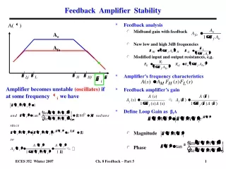
OPA277 Amplifier Stability Issuecapacitive loads Iven Xu 12/14/2013
Capacitive Loads Unity Gain Buffer Circuits
Capacitive Loads – Unity Gain Buffers - Results NG = 1V/V = 0dB
Method 1: Riso - Results Theory: Adds a zero to the Loaded AOL response to cancel the pole
Method 1: Riso - Results When to use: Works well when DC accuracy is not important, or when loads are very light
Method 1: Riso - Design Ensure Good Phase Margin: 1.) Find: fcl and f(AOL = 20dB) 2.) Set Riso to create AOL zero: Good: f(zero) = Fcl for PM ≈ 45 degrees. Better: f(zero) = F(AOL = 20dB) will yield slightly less than 90 degrees phase margin fcl = 222.74kHz f(AOL = 20dB) = 70.41kHz
Method 1: Riso - Design Ensure Good Phase Margin: Test fcl = 222.74kHz →Riso = 0.715Ohms f(AOL = 20dB) = 70.41kHz → Riso = 2.26Ohms
Method 1: Riso - Design Prevent Phase Dip: Place the zero less than 1 decade from the pole, no more than 1.5 decades away Good: 1.5 Decades: F(zero) ≤ 35*F(pole) → Riso ≥ Ro/34 →70° Phase ShiftBetter: 1 Decade: F(zero) ≤ 10*F(pole) → Riso ≥ Ro/9 → 55° Phase Shift
Method 1: Riso - Design Prevent Phase Dip: Ratio of Riso to Ro If Riso ≥ 2*Ro →F(zero) = 1.5*F(pole) →~10° Phase Shift **Almost completely cancels the pole.
Method 1: Riso – Design Summary Summary: 1.) Ensure stability by placing Fzero ≤ F(AOL=20dB) 2.) If Fzero is > 1.5 decades from F(pole) then increase Riso up to at least Ro/34 3.) If loads are very light consider increasing Riso > Ro for stability across all loads
Method 1: Riso - Disadvantage Disadvantage: Voltage drop across Riso may not be acceptable
Method 2: Riso + Dual Feedback Theory: Features a low-frequency feedback to cancel the Riso drop and a high-frequency feedback to create the AOL pole and zero.
Method 2: Riso + Dual Feedback When to Use: Only practical solution for very large capacitive loads ≥ 10uF When DC accuracy must be preserved across different current loads
Method 2: Riso + Dual Feedback - Design Ensure Good Phase Margin: 1.) Find: fcl and f(AOL = 20dB) 2.) Set Riso to create AOL zero: Good: f(zero) = Fcl for PM ≈ 45 degrees. Better: f(zero) = F(AOL = 20dB) will yield slightly less than 90 degrees phase margin 3.) Set Rf so Rf >>Riso Rf ≥ (Riso * 100) 4.) Set Cf ≥ (200*Riso*Cload)/Rf fcl = 222.74kHz f(AOL = 20dB) = 70.41kHz
Method 2: Riso + Dual Feedback - Summary Ensure Good Phase Margin (Same as “Riso” Method): 1.) Set Riso so f(zero) = F(AOL = 20dB) 2.) Set Rf: Rf ≥ (Riso * 100) 3.) Set Cf: Cf ≥ (200*Riso*Cload)/Rf